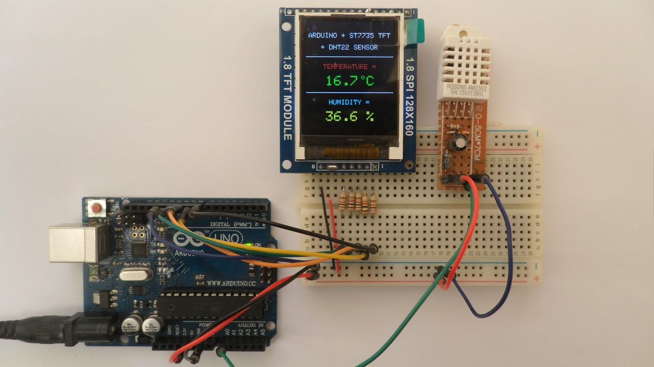
This post shows how to interface Arduino UNO board with DHT22 digital humidity and temperature sensor.
The Arduino reads temperature (in °C) & humidity (in rH%) values from the DHT22 sensor and print their values on ST7735 TFT display.
The ST7735 TFT used in this project is a color display which has a resolution of 128×160 pixel and it communicates with the master device using SPI (Serial Peripheral Interface) protocol.
To see how to interface Arduino with ST7735 TFT display, visit the following post:
Arduino ST7735 1.8″ TFT display example
And for interfacing Arduino with DHT22 sensor, see the post below:
Arduino with DHT22 sensor and LCD
Hardware Required:
- Arduino board
- ST7735S (ST7735R) TFT screen
- DHT22 (AM2302, RHT03 …) humidity and temperature sensor —-> datasheet
- 5 x 1k ohm resistor
- 4.7k ohm resistor
- Breadboard
- Jumper wires
Interfacing Arduino with ST7735 TFT and DHT22 sensor circuit:
Project circuit diagram is shown below.
The DHT22 sensor has 4 pins (from left to right):
VCC: connected to Arduino 5V pin,
Data pin: connected to Arduino analog pin 0 (A0),
Not connected pin,
GND: connected to Arduino GND pin.
A pull-up resistor of 4.7k ohm is required because the DHT22 sensor output is open drain.

The ST7735S shown in project circuit diagram has 8 pins: (from right to left): RST (reset), CE (chip enable), DC (or D/C: data/command), DIN (data in), CLK (clock), VCC (5V or 3.3V), BL (back light) and Gnd (ground).
Normally the ST7735 display works with 3.3V only, but many boards of this display have a built-in 3.3V regulator (AMS1117 3V3) like the one shown in the circuit diagram. This regulator supplies the display controller with 3.3V from 5V source.
All Arduino UNO board output pins are 5V, connecting a 5V pin directly to the ST7735 display board may damage its controller circuit. To avoid that, I connected each control line of the display to the Arduino board through 1k ohm resistor.
So, the ST7735 display is connected to the Arduino board as follows (each one through 1k resistor):
RST pin is connected to Arduino digital pin 8,
CS pin is connected to Arduino digital pin 9,
D/C pin is connected to Arduino digital pin 10,
DIN pin is connected to Arduino digital pin 11,
CLK pin is connected to Arduino digital pin 13.
Arduino with ST7735 display and DHT22 sensor code:
The following Arduino code requires 3 libraries from Adafruit Industries:
The first library is a driver for the ST7735 TFT display, download link is below:
Adafruit ST7735 display library
The 2nd library is Adafruit graphics library which can be downloaded from the following link
Adafruit graphics library —-> direct link
The third one is for the DHT22 sensor:
Adafruit DHT library —-> direct link
After the download, go to Arduino IDE —> Sketch —> Include Library —> Add .ZIP Library … and browse for the .zip file (previously downloaded).
The same thing for the other library files.
The previous 3 libraries are included in the main code as follows:
1 2 3 | #include <Adafruit_GFX.h> // include Adafruit graphics library #include <Adafruit_ST7735.h> // include Adafruit ST7735 TFT library #include <DHT.h> // include DHT library |
The ST7735 TFT display is connected to Arduino hardware SPI module pins (clock and data), the other pins which are: RST (reset), CS (chip select) and DC (data/command) are defined as shown below:
1 2 3 | #define TFT_RST 8 // TFT RST pin is connected to arduino pin 8 #define TFT_CS 9 // TFT CS pin is connected to arduino pin 9 #define TFT_DC 10 // TFT DC pin is connected to arduino pin 10 |
The definition of DHT22 data pin and the initialization of the DHT library:
1 2 3 | #define DHTPIN A0 // DHT22 data pin is connected to Arduino analog pin 0 #define DHTTYPE DHT22 // DHT22 sensor is used DHT dht22(DHTPIN, DHTTYPE); // initialize DHT library |
Rest of code is described through comments.
Full Arduino code:
1 2 3 4 5 6 7 8 9 10 11 12 13 14 15 16 17 18 19 20 21 22 23 24 25 26 27 28 29 30 31 32 33 34 35 36 37 38 39 40 41 42 43 44 45 46 47 48 49 50 51 52 53 54 55 56 57 58 59 60 61 62 63 64 65 66 67 68 69 70 71 72 73 74 75 76 77 78 79 80 81 | /* * Arduino interface with ST7735 color TFT (128x160 pixel) display and * DHT22 (AM2302) digital humidity and temperature sensor. * This is a free software with NO WARRANTY. * http://simple-circuit.com/ */ #include <Adafruit_GFX.h> // include Adafruit graphics library #include <Adafruit_ST7735.h> // include Adafruit ST7735 TFT library #include <DHT.h> // include DHT library #define TFT_RST 8 // TFT RST pin is connected to arduino pin 8 #define TFT_CS 9 // TFT CS pin is connected to arduino pin 9 #define TFT_DC 10 // TFT DC pin is connected to arduino pin 10 // initialize ST7735 TFT library Adafruit_ST7735 tft = Adafruit_ST7735(TFT_CS, TFT_DC, TFT_RST); #define DHTPIN A0 // DHT22 data pin is connected to Arduino analog pin 0 #define DHTTYPE DHT22 // DHT22 sensor is used DHT dht22(DHTPIN, DHTTYPE); // initialize DHT library void setup(void) { tft.initR(INITR_BLACKTAB); // initialize a ST7735S chip, black tab tft.fillScreen(ST7735_BLACK); // fill screen with black color tft.drawFastHLine(0, 50, tft.width(), ST7735_WHITE); // draw horizontal white line at position (0, 50) tft.drawFastHLine(0, 102, tft.width(), ST7735_WHITE); // draw horizontal white line at position (0, 102) tft.setTextColor(ST7735_WHITE, ST7735_BLACK); // set text color to white and black background tft.setTextSize(1); // text size = 1 tft.setCursor(4, 16); // move cursor to position (4, 16) pixel tft.print("ARDUINO + ST7735 TFT"); tft.setCursor(22, 33); // move cursor to position (22, 33) pixel tft.print("+ DHT22 SENSOR"); tft.setTextColor(ST7735_RED, ST7735_BLACK); // set text color to red and black background tft.setCursor(25, 61); // move cursor to position (25, 61) pixel tft.print("TEMPERATURE ="); tft.setTextColor(ST7735_CYAN, ST7735_BLACK); // set text color to cyan and black background tft.setCursor(34, 113); // move cursor to position (34, 113) pixel tft.print("HUMIDITY ="); tft.setTextSize(2); // text size = 2 // initialize DHT22 sensor dht22.begin(); } // main loop void loop() { char _buffer[7]; // read humidity int humi = dht22.readHumidity() * 10; // read temperature int temp = dht22.readTemperature() * 10; // print temperature (in °C) if(temp < 0) // if temperature < 0 sprintf(_buffer, "-%02u.%1u", abs(temp)/10, abs(temp) % 10); else // temperature >= 0 sprintf(_buffer, " %02u.%1u", temp/10, temp % 10); tft.setTextColor(ST7735_GREEN, ST7735_BLACK); // set text color to green and black background tft.setCursor(17, 78); tft.print(_buffer); tft.drawCircle(83, 80, 2, ST7735_GREEN); // print degree symbol ( ° ) tft.setCursor(89, 78); tft.print("C"); // print humidity (in %) if(humi >= 1000) // if humidity >= 100.0 % sprintf(_buffer, "%03u.%1u %%", humi/10, humi % 10); else sprintf(_buffer, " %02u.%1u %%", humi/10, humi % 10); tft.setTextColor(ST7735_YELLOW, ST7735_BLACK); // set text color to yellow and black background tft.setCursor(17, 130); tft.print(_buffer); delay(1000); // wait a second } // end of code. |
Discover more from Simple Circuit
Subscribe to get the latest posts sent to your email.


Why dont you upload movie about circuit operation?