The microcontroller PIC16F877A has 8 ADC (Analog to Digital Converter) channels (–PIC16F877A datasheet–). The resolution of the PIC16F877A ADC module is 10-bit, which means the analog value after conversion is stored as a 10-bit number that varies from 0 to 1023 (0x3FF). The ADD module has high and low-voltage reference input that is software selectable to some combination of VDD, VSS, RA2 or RA3.
PIC16F877A ADC example with CCS C compiler:
This is an example to start with the ADC module, example circuit schematic is shown below:
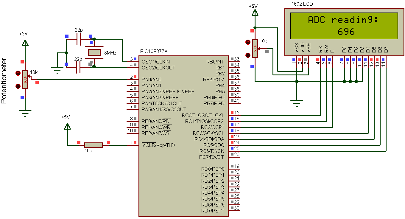
The LCD used to display the analog value after conversion where channel 0 (RA0) is the analog input and analog signal can be changed from the potentiometer. The output analog voltage of the potentiometer varies from 0V to 5V. The reference voltage is set to VDD (+5V) and GND (through software). The microcontroller must be supplied with 5V (on pins VDD and VSS).
To know how to use LCD display with PIC16F877A microcontroller see the following topic:
Interfacing PIC16F877A with LCD using CCS C compiler
PIC16F877A ADC example CCS C code:
This is the C code used for this example with some comments.
1 2 3 4 5 6 7 8 9 10 11 12 13 14 15 16 17 18 19 20 21 22 23 24 25 26 27 28 29 30 31 32 33 | // PIC16F877A ADC CCS C example //LCD module connections #define LCD_RS_PIN PIN_C0 #define LCD_RW_PIN PIN_C1 #define LCD_ENABLE_PIN PIN_C2 #define LCD_DATA4 PIN_C3 #define LCD_DATA5 PIN_C4 #define LCD_DATA6 PIN_C5 #define LCD_DATA7 PIN_C6 //End LCD module connections #include <16F877A.h> #device ADC=10 #use delay(crystal=8000000) #include <lcd.c> unsigned int16 i; void main(){ lcd_init(); // Initialize LCD module setup_adc(ADC_CLOCK_DIV_32); // Set ADC conversion time to 32Tosc setup_adc_ports(AN0); // Configure AN0 as analog set_adc_channel(0); // Select channel 0 input delay_ms(100); // Wait 100ms lcd_gotoxy(3, 1); // Go to column 3 row 1 lcd_putc("ADC reading:"); while(TRUE){ i = read_adc(); lcd_gotoxy(7, 2); // Go to column 7 row 2 printf(lcd_putc,"%4Lu",i); // Write i with 4 numbers max delay_ms(10); // Wait 10ms } } |
PIC16F877A ADC example video:
The following video shows our example in a real hardware circuit.
Discover more from Simple Circuit
Subscribe to get the latest posts sent to your email.

GREAT TUTORIAL, but where can find lcd.c file?