This topic shows how to build a simple infra-red remote controlled DC motor using PIC18F4550 microcontroller, L293D motor driver chip and CCS PIC C compiler. This controller control motor speed and rotation direction from IR remote control uses RC-5 protocol.
Related topics:
DC motor control with PIC18F4550 and L293D – Proteus simulation
RC-5 remote control decoder with PIC18F4550 and CCS C
The RC5 has 14 bits per 1 code transmission, the 14 bits can be divided into 4 parts:
The first 2 bits are start bits and they are always logic 1.
The third bit called toggle bit, it can be logic 1 or logic 0.
The next 5 bits are address bits, each device type has its address number for example TV address number is 0, CD player address = 20 …………
And the last 6 bits are command bits, each button has its command number.
For the same device for example TV all the remote control buttons has the same address but each button has its command.
The toggle bit changes whenever a button is pressed.
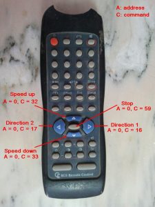
The remote control used in this project is a TV remote control which has an address = 0.
In this project toggle bit is not used which means only address and command quantities are used. The following image shows the used buttons with the corresponding address and command numbers for each button.
IR remote controlled DC motor with PIC18F4550 circuit:
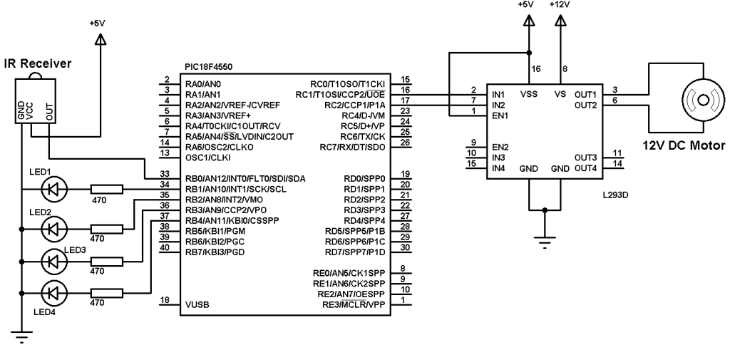
The IR receiver is used to receive the IR signals transmitted from the remote control and convert this signals to a digital data (logic 0 and logic 1). The microcontroller PIC18F4550 reads digital data from the IR receiver. LED1 blinks when RC-5 IR protocol is received.
LED2 indicates maximum speed. LED3 and LED4 indicates motor rotation direction.
L293D chip is used as a motor driver. The nominal voltage of the motor is 12V as well as L293D VS input voltage. L293D VS voltage should be the same as the motor voltage and L293D VSS voltage is +5V.
The PIC18F4550 microcontroller must be supplied with 5V on pins VDD and VSS.
PIC18F4550 CCP1 and CCP2 modules are used as PWM modules which allows us to control motor speed as well as direction of rotation. PWM frequency is 500Hz.
IR remote controlled DC motor with PIC18F4550 CCS C code:
PIC18F4550 Timer2 is configured to generate a PWM frequency of 500Hz and the microcontroller is configured to run with 8MHz internal oscillator.
1 2 3 4 5 6 7 8 9 10 11 12 13 14 15 16 17 18 19 20 21 22 23 24 25 26 27 28 29 30 31 32 33 34 35 36 37 38 39 40 41 42 43 44 45 46 47 48 49 50 51 52 53 54 55 56 57 58 59 60 61 62 63 64 65 66 67 68 69 70 71 72 73 74 75 76 77 78 79 80 81 82 83 84 85 86 87 88 89 90 91 92 93 94 95 96 97 98 99 100 101 102 103 104 105 106 107 108 109 110 111 112 113 114 115 116 117 118 119 120 121 122 123 124 125 126 127 | // Remote controlled DC motor with PIC18F4550 CCS C code // TV RC5 IR remote control used #include <18F4550.h> #fuses NOMCLR INTRC_IO #use delay(clock = 8000000) #use fast_io(B) #use fast_io(C) int1 toggle; unsigned int8 count, i, j, address, command; short remote_read(){ count = 0; // Check if the received signal uses RC5 protocol while((input(PIN_B0) == 0) && (count < 20)){ count++; delay_us(50);} if( (count > 20) || (count < 14)) // Signal doesn't use RC5 protocol return false; // Return count = 0; while((input(PIN_B0)) && (count < 20)){ count++; delay_us(50);} if( (count > 20) || (count < 14)) // Signal doesn't use RC5 protocol return false ; // Return count = 0; while((input(PIN_B0) == 0) && (count < 40)){ count++; delay_us(50);} if( (count > 40) || (count < 14)) // Signal doesn't use RC5 protocol return false ; // Return // End check (The received signal uses RC5 protocol) if(count > 30) delay_us(400); else delay_us(1300); output_high(PIN_B1); // Toggle RB1 LED for(i = 0; i < 12; i++){ if(i == 0){ if(input(PIN_B0) == 1) toggle = 0; else toggle = 1; } else { if(i < 6){ //Read address bits if(input(PIN_B0) == 1) bit_clear(address, (5 - i)); //Clear bit (5-i) else bit_set(address, (5 - i)); //Set bit (5-i) } else { //Read command bits if(input(PIN_B0) == 1) bit_clear(command, (11 - i)); //Clear bit (11-i) else bit_set(command, (11 - i)); //Set bit (11-i) } } delay_us(1778); } address &= 0x1F; command &= 0x3F; return true; } void main(){ setup_oscillator(OSC_8MHZ); // Set internal oscillator to 8MHz setup_adc_ports(NO_ANALOGS); // Configure AN pins as digital port_b_pullups(TRUE); // Enable PORTB pull-ups output_b(0); // PORTB initial state set_tris_b(1); // Configure RB0 pin as input output_c(0); // PORTC initial state set_tris_c(0); // Configure PORTC pins as outputs setup_timer_2(T2_DIV_BY_16, 250, 1); // Set PWM frequency to 500Hz delay_ms(100); // Wait 100ms while(TRUE){ output_low(PIN_B1); while(input(PIN_B0)); // Wait until RB0 pin falls if(remote_read()){ if((address == 0) && (command == 16) && (input(PIN_B3) == 0)){ // Direction 1 output_b(0); // Both LEDs OFF setup_ccp1(CCP_OFF); // CCP1 OFF setup_ccp2(CCP_OFF); // CCP2 OFF output_c(0); // PORTC pins low delay_ms(100); // Wait 100ms setup_ccp1(CCP_PWM); // Configure CCP1 as PWM set_pwm1_duty(j); // Set pwm1 duty cycle output_high(PIN_B3); // RB3 LED ON if(j > 250) output_high(PIN_B2); // RB2 LED ON (speed is max) } if((address == 0) && (command == 17) && (input(PIN_B4) == 0)){ // Direction 2 output_b(0); // Both LEDs OFF setup_ccp1(CCP_OFF); // CCP1 OFF setup_ccp2(CCP_OFF); // CCP2 OFF output_c(0); // PORTC pins low delay_ms(100); // Wait 100ms setup_ccp2(CCP_PWM); // Configure CCP2 as PWM set_pwm2_duty(j); // Set pwm1 duty cycle output_high(PIN_B4); // RB4 LED ON if(j > 250) output_high(PIN_B2); // RB2 LED ON (speed is max) } if((address == 0) && (command == 32) && (j < 251)){ // Speed up j++; if(j > 250) output_high(PIN_B2); // RB2 LED ON if(input(PIN_B3)) set_pwm1_duty(j); // Set pwm1 duty cycle if(input(PIN_B4)) set_pwm2_duty(j); // Set pwm2 duty cycle } if((address == 0) && (command == 33) && (j > 0)){ // Speed down j--; output_low(PIN_B2); // RB2 LED OFF if(input(PIN_B3)) set_pwm1_duty(j); // Set pwm1 duty cycle if(input(PIN_B4)) set_pwm2_duty(j); // Set pwm2 duty cycle } if((address == 0) && (command == 59)){ // Motor stop setup_ccp1(CCP_OFF); // CCP1 OFF setup_ccp2(CCP_OFF); // CCP2 OFF output_b(0); // Both LEDs OFF output_c(0); // PORTC pins low } } delay_ms(10); } } |
Remote controlled DC motor with PIC18F4550 video:
The following video shows a hardware circuit of this project.
Discover more from Simple Circuit
Subscribe to get the latest posts sent to your email.


