Adding a serial-in parallel-out shift register such as the popular one 74HC595 to a 7-segment display will reduce number of pins required to drive it (the display).
Basically the 7-segment display (1 digit) requires 9 pins: 8 segment pins (A, B, C, D, E, F, G and DP) + common pin. By connecting all the segment pins to a shift register, the required number of pins becomes just 3: clock pin and data pin (for the shift register) + common pin.
So, for a 4-digit 7-segment display we need just 6 pins: clock, data and 4 common pins (each digit has its individual common pin).
This topic shows how to build a simple digital counter using PIC18F46K22 microcontroller, common anode 7-segment display with 4 digits and 74HC595 shift register.
CCS C Compiler is used in this example.
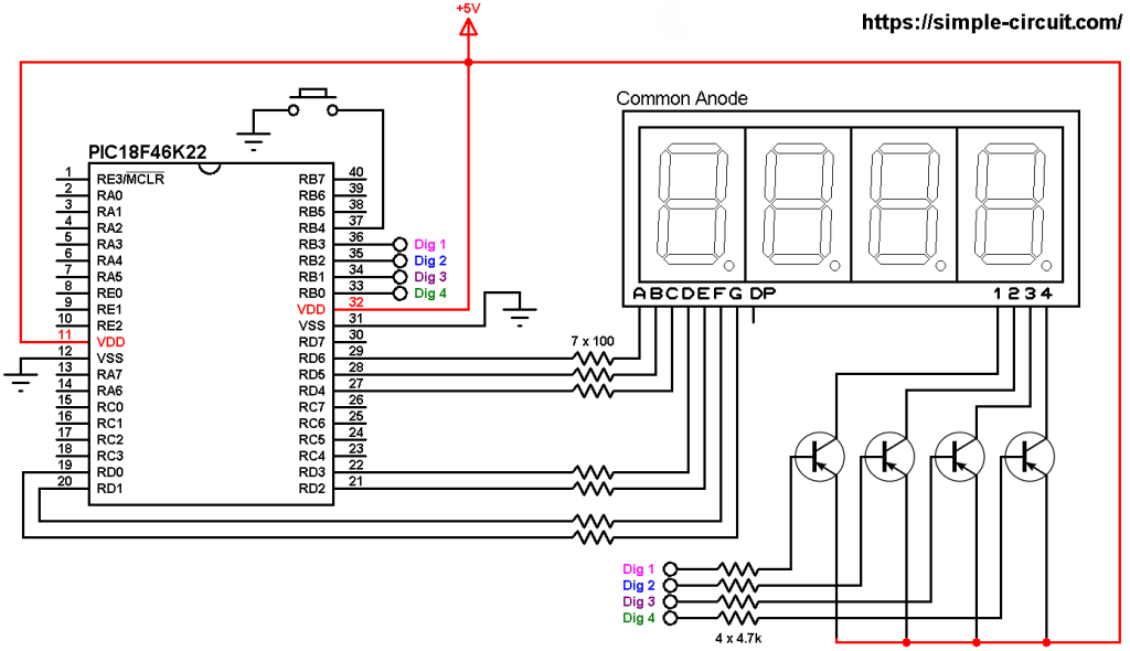
To see how to interface the PIC18F46K22 microcontroller with 7-segment display (4-digit counter example), visit the following post:
Interfacing PIC18F46K22 with 7-segment display | 4-Digit counter example
Hardware Required:
- PIC18F46K22 microcontroller —-> datasheet
- 4-Digit common anode 7-segment display
- 74HC595 shift register —-> datasheet
- 4 x PNP transistor (2SA1015, 2S9015, 2N3906 …)
- 8 x 100 ohm resistor
- 4 x 4.7k ohm resistor
- Push button
- 5V source
- Breadboard
- Jumper wires
- PIC MCU Programmer (PICkit 3, PICkit 4…)
7-Segment display with 74HC595 shift register circuit:
The image below shows our example circuit schematic diagram.
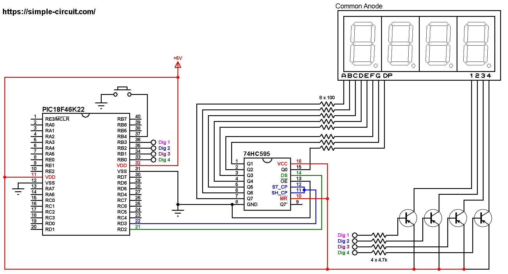
All the grounded terminals are connected together.
As shown in the circuit diagram above, all segment pins are connected to the 74HC595 output pins, each one through 100 ohm resistor, where:
Segment A … G are connected to 74HC595 pin Q7 … Q1 respectively and segment DP is connected to pin Q0.
The data pin of the 74HC595 shift register is named DS (#14) and it is connected to PIC18F46K22 pin RD2 (#21).
ST_CP (or RCLK) and SH_CP (or SRCLK) are connected together which then connected to PIC18F46K22 pin RD3 (#22), this is the clock pin.
Since the display has 4 digits, there’re 4 common pins: 1 (most left), 2, 3 and 4. Each common pin is connected to collector terminal of one transistor. Emitter terminals of the 4 transistors are connected to circuit +5V. Base terminals of the four transistors are connected to the PIC18F46K22 through 4.7k resistors.
The 4 transistors are of the same type (PNP).
The push button which is connected to PIC18F46K22 pin RB4 (#37) is used to increment the displayed number.
In this project the PIC18F46K22 microcontroller runs with its internal oscillator @ 8 MHz, MCLR pin is configured as an input pin.
7-Segment display with 74HC595 shift register C code:
The following C code is for CCS C compiler, it was tested with version 5.0.51.
Shift register clock and data pins are defined as:
1 2 3 | // shift register pins #define clockPin PIN_D3 // clock pin #define dataPin PIN_D2 // data pin |
And the 4 common pins are defined as shown below:
1 2 3 4 5 | // common pins of the four digits definitions #define Com_1 PIN_B3 #define Com_2 PIN_B2 #define Com_3 PIN_B1 #define Com_4 PIN_B0 |
Since the 4 digits are multiplexed we need to refresh the display very quickly (display one digit at a time, others are off), for that I used Timer2 module (8-bit timer) interrupt with 1:16 prescaler and 1:2 postoscaler, this means Timer2 overflows every 2048 microseconds { 256/[8/(4 x 16)] = 256 x 8 = 2048 microseconds } and its interrupt occurred every 4096 microseconds (postoscaler = 2).
Timer2 module configuration is shown below (255 is the preload value):
1 | setup_timer_2( T2_DIV_BY_16, 255, 2 ); // enable Timer2 with prescaler=16 & postoscaler=2 |
CCS C Code:
1 2 3 4 5 6 7 8 9 10 11 12 13 14 15 16 17 18 19 20 21 22 23 24 25 26 27 28 29 30 31 32 33 34 35 36 37 38 39 40 41 42 43 44 45 46 47 48 49 50 51 52 53 54 55 56 57 58 59 60 61 62 63 64 65 66 67 68 69 70 71 72 73 74 75 76 77 78 79 80 81 82 83 84 85 86 87 88 89 90 91 92 93 94 95 96 97 98 99 100 101 102 103 104 105 106 107 108 109 110 111 112 | /* * 7-segment display with 74HC595 shift register. * 4-Digit counter example. * Common anode 7-segment display is used. * C Code for CCS C compiler. * This is a free software with NO WARRANTY. * http://simple-circuit.com/ */ // counter button definition #define button PIN_B4 // shift register pins #define clockPin PIN_D3 // clock pin #define dataPin PIN_D2 // data pin // common pins of the four digits definitions #define Com_1 PIN_B3 #define Com_2 PIN_B2 #define Com_3 PIN_B1 #define Com_4 PIN_B0 #include <18F46K22.h> #fuses NOMCLR,NOLVP,NOBROWNOUT,PUT,NOXINST #use delay(internal = 8MHz) int16 count = 0; const char seg_maps[] = { 0x03, //0 0x9F, //1 0x25, //2 0x0D, //3 0x99, //4 0x49, //5 0x41, //6 0x1F, //7 0x01, //8 0x09 //9 }; void seg_out(int8 nbr) { nbr = seg_maps[nbr]; for(int8 i = 0x80; i; i >>= 1) { if (nbr & i) output_high(dataPin); else output_low(dataPin); output_high(clockPin); output_low(clockPin); } // send another clock pulse output_high(clockPin); output_low(clockPin); } #INT_TIMER2 // Timer2 ISR void Timer2_ISR(void) { static int8 current_digit; // turn off all segments output_high(Com_1); output_high(Com_2); output_high(Com_3); output_high(Com_4); if(current_digit == 1) { seg_out(count / 1000); output_low(Com_1); // turn on digit 1 (most left) } if(current_digit == 2) { seg_out((count / 100) % 10); output_low(Com_2); // turn on digit 2 } if(current_digit == 3) { seg_out((count / 10) % 10); output_low(Com_3); // turn on digit 3 } if(current_digit == 4) { seg_out(count % 10); output_low(Com_4); // turn on digit 4 (most right) } current_digit = (current_digit % 4) + 1; } // main function void main() { setup_oscillator(OSC_8MHZ); // set internal oscillator to 8MHz port_b_pullups(0x10); // enable RB4 internal pull-up enable_interrupts(GLOBAL); // enable global interrupts clear_interrupt(INT_TIMER2); // clear Timer2 interrupt flag bit enable_interrupts(INT_TIMER2); // enable Timer2 interrupt setup_timer_2( T2_DIV_BY_16, 255, 2 ); // enable Timer2 with prescaler=16 & postoscaler=2 while(TRUE) { if( !input(button) ) { // if button is pressed count++; if(count > 9999) count = 0; delay_ms(200); // wait 200 milliseconds } } } // end of code. |
Discover more from Simple Circuit
Subscribe to get the latest posts sent to your email.