This small project shows how to make a simple wave audio player using PIC16F887 microcontroller and SD card. The WAV audio file used in this project is 8000 Hz, 8-bit stereo (2 channels).
Hardware Required:
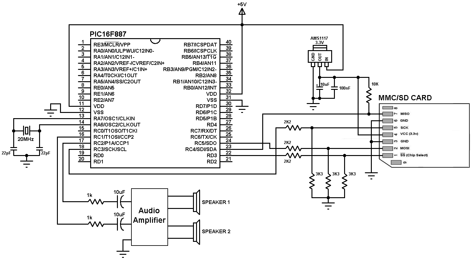
- PIC16F887 microcontroller —> datasheet
- SD card (formatted with FAT16 or FAT32 file system)
- ASM1117 3.3 voltage regulator
- Audio amplifier (ex: PC speaker, LM386……)
- Speaker
- 20 MHz crystal oscillator
- 2 x 22pF ceramic capacitors
- 3 x 3.3K ohm resistor
- 3 x 2.2K ohm resistor
- 10K ohm resistor
- 2 x 1K ohm resistor
- 3 x 10uF polarized capacitor
- 100nF ceramic capacitor
- 5V Power source
- Breadboard & jumper wires
- PIC Microcontroller programmer (PICkit 2, PICkit 3…)
Wave audio player using PIC16F887 microcontroller circuit:
Project circuit schematic is the one below.
The microcontroller generates audio using PWM technique, if the wave audio file is mono (1 channel) the microcontroller will generate only 1 PWM signal (PWM1) and hence we will hear the sound from 1 speaker only. If the wave audio file is stereo both speakers will give sound.
In this project the PIC16F887 runs with 20MHz crystal oscillator which is the maximum speed of this microcontroller, MCLR pin function is disabled.
Wave audio player using PIC16F887 microcontroller C code:
The C code below was tested with CCS C compiler versions 5.051.
In this project I used the FAT library (FAT16 and FAT32), its source file can be found in the the following topic:
SD card FAT library for CCS C compiler
I tested this project with FAT32 8 GB and FAT16 2 GB micro-SD cards.
The name of the wave audio file which I used was mywav (mywav.wav with the extension), its sample rate is 8000 Hz with 2 channels (stereo).
First of all I initialized the SD card using the function: sdcard_init(); this function return 0 if the initialization was OK and non-zero if there was an error. After the initialization of the SD card I initialized the FAT file system using the function fat_init(); and then I opened the wave audio file with the pre-selected name mywav.wav, all the three previous function returns 0 if OK and no-zero if error.
If the initialization of the SD card, the FAT system and opening of the file were OK that means the variable which named ok = 0 and playing the wave file starts using the function play(); .
To detect if the wave file is mono (1 channel) or stereo (2 channels), the microcontroller reads byte number 22 of the wave file using the function :
sdcard_read_byte(address_pointer + 22, &channel_count);
where the variable address_pointer belongs to the FAT library, this variable allows me to know the starting address of the wave audio file.
If the wave file is mono ==> channel_count =1 and if it is stereo ==> channel_count = 2.
I set the data buffer to 16 so each time the microcontroller reads 32 bytes from the SD card. The data buffer can be less or higher than 16.
The function fat_read_data(16, data) keeps reading file data from the SD card until it returns 1 which means end of the wave file is reached.
The wave file must be 8-bit and for that I configured the PWM outputs to give the maximum frequency with 8-bit resolution, for that I configured Timer2 module as shown below:
setup_timer_2(T2_DIV_BY_1, 63, 1);
The resolution of the PWM signal can be calculated using the function:
PWM Resolution = Log[(PR2 + 1)4]/Log(2) = Log[(63 + 1)4]/Log(2) = 8
The PWM frequency should be as higher as possible and with the previous configuration I got a PWM frequency of 78.125 KHz. It can be calculated with the function below:
PWM_Frequency = Fosc/[(PR2 + 1)4TMR2_Prescaler] = 2010^6/[(63 + 1)4*1] = 78.125 KHz.
If channel_count = 2 the 2nd PWM duty cycle also will be updated and the sound will be generated from PWM1 (RC2) and PWM2 (RC1) outputs (left and right).
Now how did I used Timer1 module and the wave file sample rate (8000 Hz):
the PWM duty cycles have to be updated every 125 us ( = 1/8000Hz), for that I used Timer1 to make the MCU waits for 125 us. In this example I didn’t use Timer1 interrupt.
I configured Timer1 module to increment on every MCU cycle (0.2 us) and to compute Timer1 value (values between 2 updates) I used the function:
Fosc/[sample rate * 4) = 20 * 10^6/(8000 * 4) = 625
where sample rate = 18000 and Fosc = 20 * 10^6 .
In this example I used the value 500 instead of 625 because I got a slow audio streaming (i.e: some instructions are spent on loops).
The complete C code is the one below.
1 2 3 4 5 6 7 8 9 10 11 12 13 14 15 16 17 18 19 20 21 22 23 24 25 26 27 28 29 30 31 32 33 34 35 36 37 38 39 40 41 42 43 44 45 46 47 48 49 50 51 52 53 | /* WAV Audio Player using PIC16F887 microcontroller and SD card CCS C code. FAT Library for CCS C compiler must be installed */ // SD Card module connections #define SDCARD_SPI_HW #define SDCARD_PIN_SELECT PIN_D3 // End SD card module connections #include <16F887.h> #fuses NOMCLR, HS, NOBROWNOUT, NOLVP #use delay(clock = 20MHz) #use fast_io(D) #include <FAT_Lib.c> const int8 *wav = "mywav.wav"; int1 ok = 0; int8 i, j, data[16], channel_count; void play(){ sdcard_read_byte(address_pointer + 22, &channel_count); // Read number of channels while(fat_read_data(16, data) == 0){ for(i = 0; i < 16; i++){ set_timer1(0); j = data[i]; set_pwm1_duty((int16)j); // Update PWM1 duty cycle if(channel_count == 2){ // If 2-channel wave file (stereo) i++; // increment i j = data[i]; set_pwm2_duty((int16)j); // Update PWM2 duty cycle } while(get_timer1() < 500); // Wait some time (about 125us) to update the duty cycles } } } void main(){ delay_ms(2000); setup_ccp1(CCP_PWM); // Configure CCP1 as a PWM setup_ccp2(CCP_PWM); // Configure CCP2 as a PWM set_pwm1_duty(0); // set PWM1 duty cycle to 0 set_pwm2_duty(0); // set PWM2 duty cycle to 0 setup_timer_2(T2_DIV_BY_1, 63, 1); // Set PWM frequency to maximum with 8-bit resolution setup_timer_1( T1_INTERNAL | T1_DIV_BY_1 ); // Timer1 configuration ok |= sdcard_init(); // Initialize the SD card module ok |= fat_init(); // Initialize FAT library ok |= fat_open_file(wav); // Open the wave file if(ok == 0){ play(); } set_pwm1_duty(0); // set PWM1 duty cycle to 0 set_pwm2_duty(0); // set PWM2 duty cycle to 0 } // End |
The video below shows the result of the example except that the MCU used is PIC16F877A:
Discover more from Simple Circuit
Subscribe to get the latest posts sent to your email.


Cool project! I’m trying to wrap my head around the code… Are there header files somewhere? I don’t see any configuration bits in the main file, plus it looks like you use a few functions that aren’t defined? Does it all come from the ‘FAT’ library?