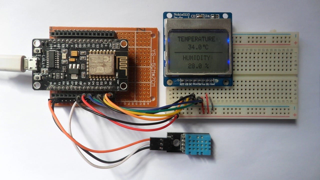
This Simple Projects post shows how to interface ESP8266 NodeMCU development board (ESP-12E) with DHT11 digital humidity & temperature sensor and Nokia 5110 LCD.
The NodeMCU reads temperature and relative humidity values from the DHT11 (RHT01) sensor and prints them (respectively in °C and RH%) on the Nokia 5110 LCD display which has a resolution of 84×48 pixel.
To see how to interface NodeMCU board with Nokia 5110 LCD, visit this post:
Interfacing ESP8266 NodeMCU with Nokia 5110 LCD
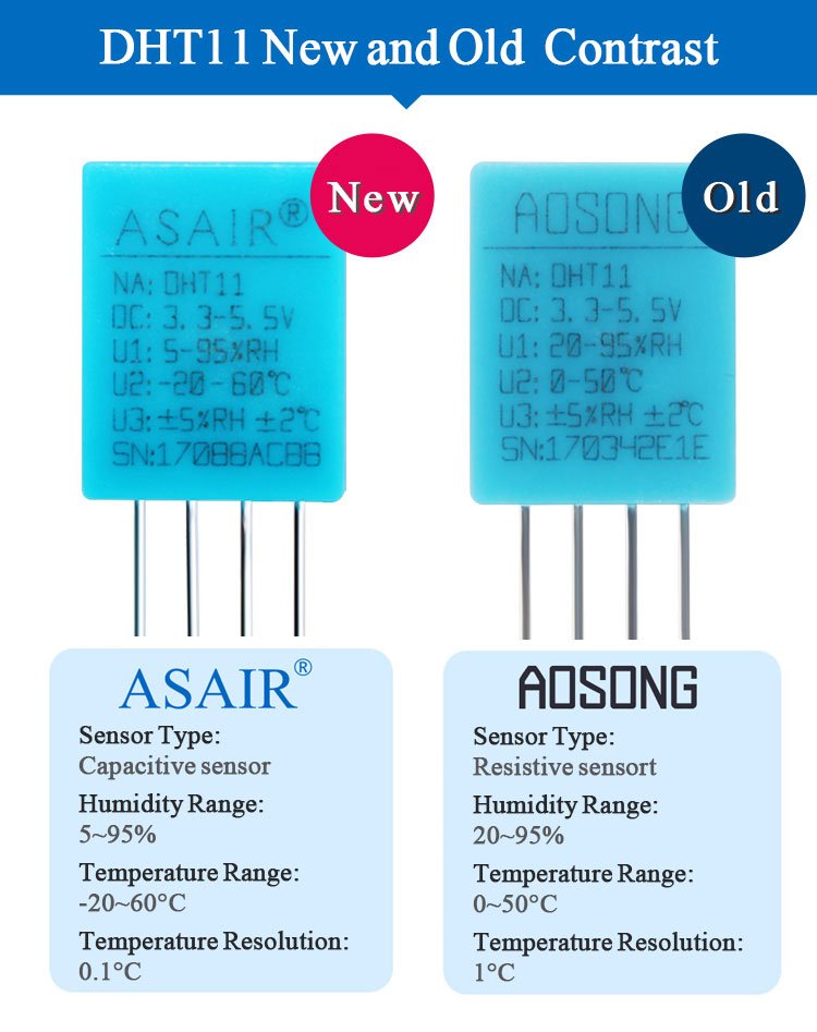
There are two types of the DHT11 sensor: old type (AOSONG) and new type (ASAIR). The differences between the 2 types are summarized below:
Seeed Studio provides a good module of the new DHT11 sensor (ASAIR version) named “Grove Temperature & Humidity Sensor”, more details in its official page:
Grove Temperature & Humidity Sensor
Hardware Required:
- NodeMCU development board
- Nokia 5110 LCD module
- DHT11 (RHT01) humidity and temperature sensor —-> datasheet
- 4.7k ohm resistor
- Micro USB cable (for programming and powering the whole circuit)
- Breadboard
- Jumper wires
NodeMCU with Nokia 5110 LCD and DHT11 sensor circuit:
The image below shows project circuit diagram.
The DHT11 sensor has 4 pins (from left to right):
Pin 1 is power supply pin, connected NodeMCU 3V3 pin,
Pin 2: data output pin, connected to NodeMCU digital pin 5 (D5),
Pin 3: not connected pin,
Pin 4: GND (ground), connected to NodeMCU GND pin.
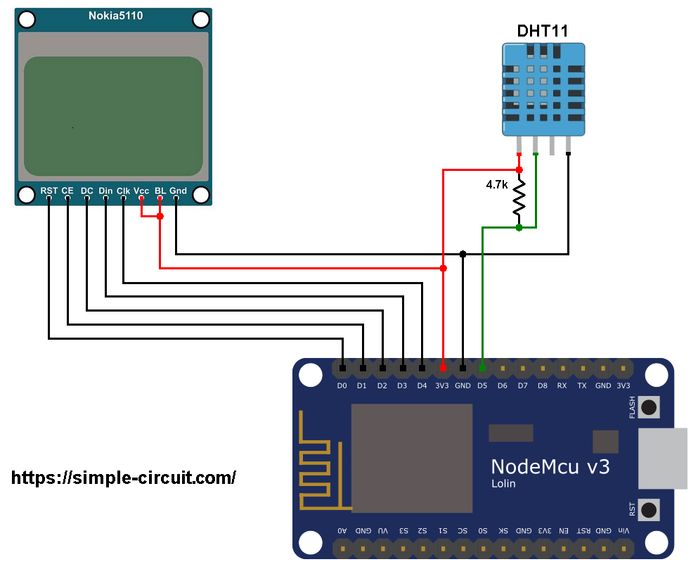
The Nokia 5110 LCD which is shown in the circuit diagram has 8 pins (from left to right): RST (reset), CE (chip enable), DC (or D/C: data/command), Din (data in), Clk (clock), VCC (3.3V), BL (back light) and Gnd (ground).
The Nokia 5110 LCD is connected to the NodeMCU board as follows:
RST (reset) pin is connected to pin D0 (ESP8266EX GPIO16),
CE (chip enable) pin is connected to pin D1 (ESP8266EX GPIO5),
DC (data/command) pin is connected to pin D2 (ESP8266EX GPIO4),
DIN (data in) pin is connected to pin D3 (ESP8266EX GPIO0),
CLK (clock) pin is connected to pin D4 (ESP8266EX GPIO2),
VCC and BL are connected to pin 3V3,
GND is connected to pin GND.
NodeMCU with Nokia 5110 LCD and DHT11 sensor code:
The following Arduino code requires 3 libraries from Adafruit Industries:
The first library is a driver for the Nokia 5110 LCD (PCD8544 controller), download link is below:
Adafruit Nokia 5110 LCD library
The 2nd library is Adafruit graphics library which can be downloaded from the following link
Adafruit graphics library —-> direct link
The 3rd one is for the DHT11 sensor:
Adafruit DHT library —-> direct link
After the download, go to Arduino IDE —> Sketch —> Include Library —> Add .ZIP Library … and browse for the .zip file (previously downloaded).
The same thing for the other library files.
The previous 3 libraries (and Arduino SPI library) are included in the main code as follows:
1 2 3 4 | #include <SPI.h> // include Arduino SPI library #include <Adafruit_GFX.h> // include adafruit graphics library #include <Adafruit_PCD8544.h> // include adafruit PCD8544 (Nokia 5110) library #include <DHT.h> // include adafruit DHT library code |
Definition of sensor type, its data pin connection and the initialization of the DHT library:
1 2 3 | #define DHTPIN D5 // DHT11 data pin is connected to NodeMCU pin D5 #define DHTTYPE DHT11 // DHT11 sensor is used DHT dht11(DHTPIN, DHTTYPE); // configure DHT library |
Rest of code is described through comments.
Full Arduino code:
1 2 3 4 5 6 7 8 9 10 11 12 13 14 15 16 17 18 19 20 21 22 23 24 25 26 27 28 29 30 31 32 33 34 35 36 37 38 39 40 41 42 43 44 45 46 47 48 49 50 51 52 53 54 55 56 57 58 59 60 61 62 63 64 65 66 67 68 69 70 71 72 73 | /************************************************************************* * * ESP8266 NodeMCU (ESP-12E) with Nokia 5110 LCD (84x48 pixel) and DHT11 * digital humidity and temperature sensor. * This is a free software with NO WARRANTY. * http://simple-circuit.com/ * ************************************************************************/ #include <SPI.h> // include Arduino SPI library #include <Adafruit_GFX.h> // include adafruit graphics library #include <Adafruit_PCD8544.h> // include adafruit PCD8544 (Nokia 5110) library #include <DHT.h> // include adafruit DHT library code // Nokia 5110 LCD module connections (CLK, DIN, D/C, CS, RST) Adafruit_PCD8544 display = Adafruit_PCD8544(D4, D3, D2, D1, D0); #define DHTPIN D5 // DHT11 data pin is connected to NodeMCU pin D5 #define DHTTYPE DHT11 // DHT11 sensor is used DHT dht11(DHTPIN, DHTTYPE); // configure DHT library void setup() { // initialize the display display.begin(); // initialize the DHT sensor dht11.begin(); // you can change the contrast around to adapt the display // for the best viewing! display.setContrast(50); display.clearDisplay(); // clear the screen and buffer display.drawFastHLine(0, 23, display.width(), BLACK); display.setTextSize(1); display.setTextColor(BLACK, WHITE); display.setCursor(6, 0); display.print("TEMPERATURE:"); display.setCursor(15, 28); display.print("HUMIDITY:"); display.display(); } // main loop void loop() { // read humidity int Humi = dht11.readHumidity() * 10; // read temperature in degree Celsius int Temp = dht11.readTemperature() * 10; // print temperature (in °C) display.setCursor(18, 12); if(Temp < 0) // if temperature < 0 display.printf("-%02u.%1u C", (abs(Temp)/10)%100, abs(Temp) % 10); else // temperature >= 0 display.printf(" %02u.%1u C", (Temp/10)%100, Temp % 10); // print degree symbol ( ° ) display.drawRect(50, 12, 3, 3, BLACK); // print humidity (in %) display.setCursor(24, 40); display.printf("%02u.%1u %%", (Humi/10)%100, Humi % 10); // now update the display display.display(); delay(1000); // wait a second } // end of code. |
Discover more from Simple Circuit
Subscribe to get the latest posts sent to your email.