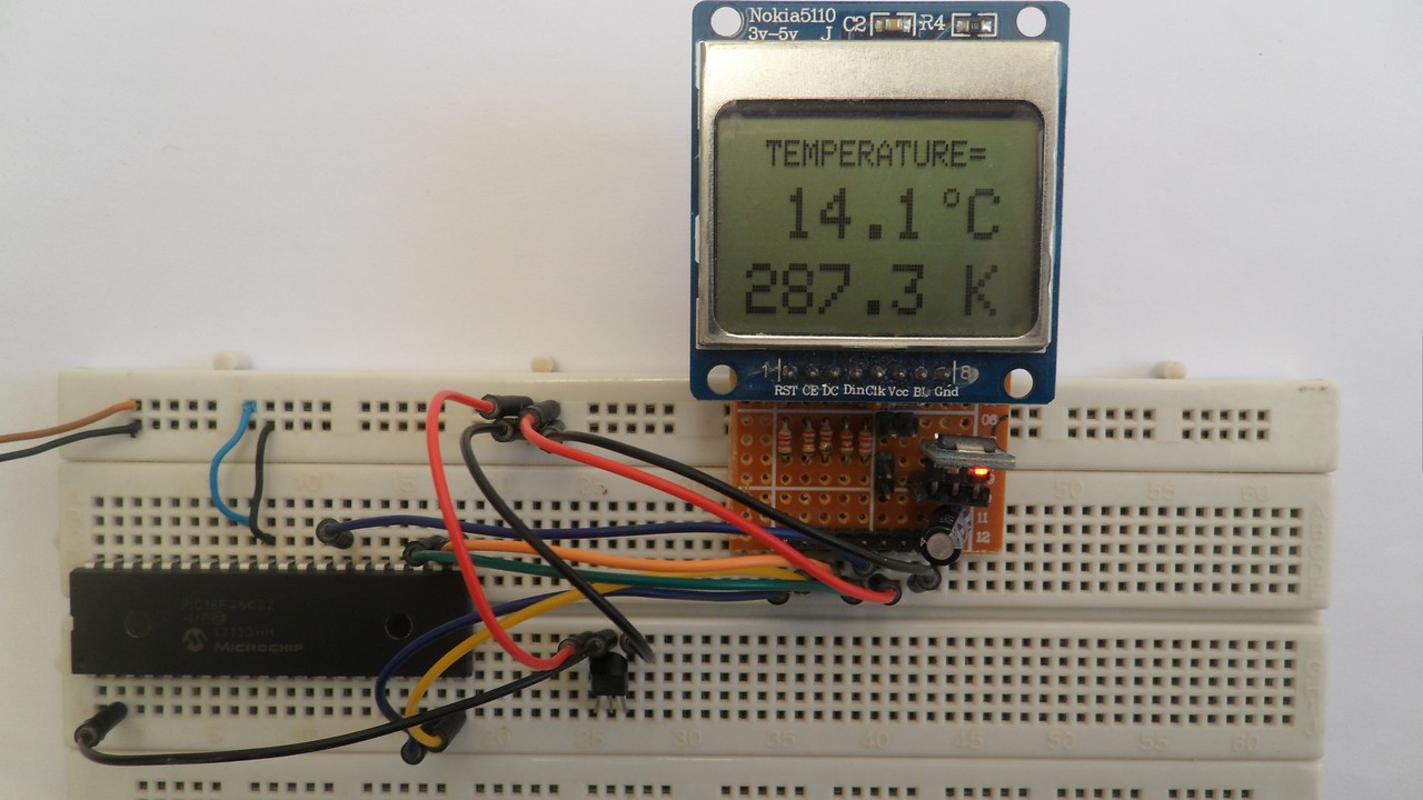
This post shows how to build a temperature measurement station using PIC18F46K22 microcontroller and LM35 analog temperature sensor from Texas Instruments.
Nokia 5110 LCD (84×48 pixel) is used to display environment temperature in degree Celsius and Kelvin.
CCS C compiler is used in this project.
To see how to interface the PIC18F4550 with the Nokia 5110 using CCS C compiler, visit the post below: Interfacing PIC18F4550 MCU with NOKIA 5110 LCD
About the LM35 temperature sensor:
The LM35 temperature sensor is a three pin device (VCC, OUT and GND) with an output voltage linearly related to Centigrade temperature. Since the LM35 output varies with dependent to the temperature, we need an ADC (Analog-to-Digital Converter) module to measure this voltage. The PIC18F46K22 microcontroller has one ADC module with 10-bit resolution.
The LM35 output has linear +10mV/°C scale factor means the following:
If the output voltage = 10mV —> temperature = 1°C
If the output voltage = 100mV —> temperature = 10°C
If the output voltage = 200mV —> temperature = 20°C
If the output voltage = 370mV —> temperature = 37°C
and so on.
LM35 Futures (from datasheet):
- Calibrated Directly in ° Celsius (Centigrade)
- Linear + 10 mV/°C Scale Factor
- 0.5°C Ensured Accuracy (at +25°C)
- Rated for Full −55°C to +150°C Range
- Suitable for Remote Applications
- Low Cost Due to Wafer-Level Trimming
- Operates from 4 to 30 V
- Less than 60-μA Current Drain
- Low Self-Heating, 0.08°C in Still Air
- Nonlinearity Only ±¼°C Typical
- Low Impedance Output, 0.1 Ω for 1 mA Load
The ADC module converts analog data into digital data. The PIC18F46K22 MCU has a 10-bit ADC module and a built-in fixed voltage reference (FVR) module which makes it a good choice for this application. With the fixed voltage reference we get a very good results.
Normally negative and positive references of the ADC module are VSS and VDD respectively, but VDD is not exactly equal to 5.00V, hence we should use the fixed voltage reference as a positive reference of the ADC module.
The PIC18F46K22 has 3 fixed voltage references: 1.024V, 2.048V and 4.096V. For example if we set the fixed voltage reference to 4.096V and the ADC module is configured so that the negative and the positive references are VSS and FVR respectively, in this case the equivalent 10-bit digital value of 4.096 is 1023 and 3.00V is 3.00 * 1023/4.096 = 749 , and so on.
In this project I used FVR = 1.024V because the LM35 output is generally less than 1V and also it gave me better result (let’s say higher resolution). Now the ADC module works in the interval between 0 and 1.024V.
Hardware Required:
- PIC18F46K22 microcontroller —-> datasheet
- Nokia 5110 LCD screen
- LM35 temperature sensor —-> datasheet
- AMS1117 3V3 voltage regulator
- 10 uF capacitor
- 100 nF ceramic capacitor
- 5 x 3.3k ohm resistor
- 5 x 2.2k ohm resistor
- 5V source
- Breadboard
- Jumper wires
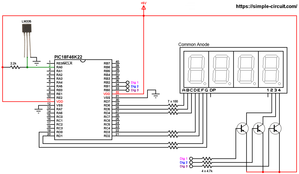
PIC18F46K22 MCU with Nokia 5110 LCD and LM35 sensor circuit:
The image below shows project circuit diagram.
The LM35 sensor has 3 pins (from left to right):
Pin 1 is power supply pin, connected to circuit +5V,
Pin 2: output pin,
Pin 3: GND (ground), connected to circuit ground.
The output pin of the LM35 sensor is connected to pin RA0 which is analog channel 0 (AN0).
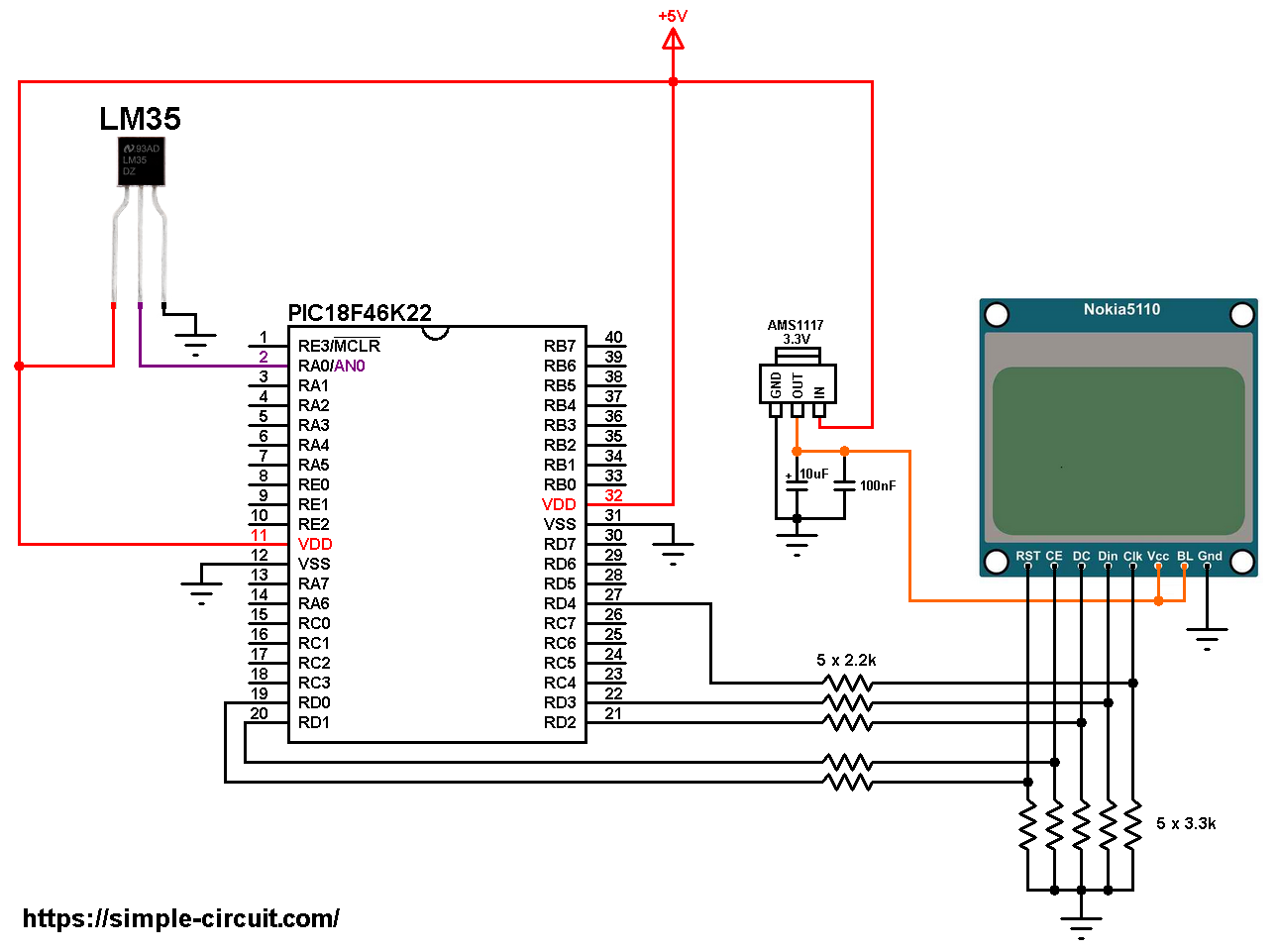
All the grounded terminals are connected together.
The Nokia 5110 which is shown in the circuit diagram has 8 pins (from left to right): RST (reset), CE (chip enable), DC (or D/C: data/command), Din (data in), Clk (clock), VCC (3.3V), BL (back light) and Gnd (ground).
The Nokia 5110 LCD works with 3.3V only (power supply and control lines). The LCD module is supplied with 3.3V which comes from the AMS1117 3V3 voltage regulator, this regulator steps down the 5V into 3.3V.
All PIC18F46K22 microcontroller output pins are 5V, connecting a 5V pin to the Nokia 5110 LCD may damage its controller circuit!
To connect the PIC18F46K22 to the LCD module, I used voltage divider for each line which means there are 5 voltage dividers. Each voltage divider consists of 2.2k and 3.3k resistors, this drops the 5V into 3V which is sufficient.
So, the Nokia 5110 LCD pins are connected to PIC18F46K22 MCU as follows (each one through voltage divider):
RST (reset) pin is connected to pin RD0 (#19)
CE (chip enable) pin is connected to pin RD1 (#20)
DC (data/command) pin is connected to pin RD2 (#21)
DIN (data in) pin is connected to pin RD3 (#22)
CLK (clock) pin is connected to pin RD4 (#27)
VCC and BL are connected to AMS1117 3V3 regulator output pin and GND is connected to circuit ground (0V).
In this project the PIC18F46K22 microcontroller runs with its internal oscillator @ 16 MHz, MCLR pin is configured as an input pin.
PIC18F46K22 MCU with Nokia 5110 LCD and LM35 sensor C code:
The following C code is for CCS C compiler, it was tested with version 5.051.
To be able to compile the C code below with no error, a driver (library) for the Nokia 5110 LCD (PCD8544 controller) is required, its full name (with extension) is NOKIA5110.c, download link is the one below:
Nokia 5110 LCD CCS C library download
after the download of the library file, add it to project folder or CCS C compiler drivers folder.
Programming hints:
The connection of the LCD pins: RST, CE, DC, DIN and CLK is defined in the code as shown below where software SPI is used:
1 2 3 4 5 6 | // define LCD module connections #define LCD_RST PIN_D0 // reset pin, optional! #define LCD_CS PIN_D1 // chip select pin, optional! #define LCD_DC PIN_D2 // data/command pin #define LCD_DAT PIN_D3 // data-in pin (MOSI) #define LCD_CLK PIN_D4 // clock pin |
Software SPI is initialized as shown below:
1 | #use SPI(DO = LCD_DAT, CLK = LCD_CLK, MODE = 0, BITS = 8, STREAM = LCD_STREAM) |
The internal fixed voltage reference (FVR) of the PIC18F46K22 microcontroller is set to 1.024V using the following line:
1 | setup_vref(VREF_1v024); // set FVR to 1.024V // FVR: Fixed Voltage Reference |
The ADC module is configured so that it uses its internal clock, voltage references (negative and positive) are set to VSS and FVR respectively where the FVR is the one previously set to 1.024V.
The LM35 output pin is connected to AN0 channel. All these configurations are done in the code as shown below:
1 2 3 4 | setup_adc(ADC_CLOCK_INTERNAL); // set ADC module clock to internal // configure AN0 pin as analog & set voltage references to: VSS - FVR(1.024V) setup_adc_ports(sAN0 | VSS_FVR); set_adc_channel(sAN0); // select AN0 channel |
PIC18F46K22 ADC module is used with 10-bit resolution which means the digital value of the input analog voltage varies between 0 (0V) and 1023 (1.024V).
The digital value represents the temperature in tenths °Celsius (output value of “274” equals 27.4 °Celsius).
The temperature in tenths Kelvin = (tenth °Celsius) + 2732 (because: K = °C + 273.16).
To get the actual value of each quantity we’ve to divide it by 10. The line below shows an example for temperature in Kelvin:
1 | printf(LCD_Print, "%03Lu.%1Lu K", tKelvin/10, tKelvin % 10); |
We get the first 3 digits by dividing the tenths value by 10, and the tenths number (number after the decimal point) of the actual temperature value is equal to the reminder of that division (tenths value % 10).
The resolution of this thermometer is 0.1 °C.
CCS C Code:
1 2 3 4 5 6 7 8 9 10 11 12 13 14 15 16 17 18 19 20 21 22 23 24 25 26 27 28 29 30 31 32 33 34 35 36 37 38 39 40 41 42 43 44 45 46 47 48 49 50 51 52 53 54 55 56 57 58 59 60 61 62 63 64 65 66 67 68 69 70 71 72 | /* * Interfacing PIC18F46K22 microcontroller with Nokia 5110 LCD (84x48 Pixel) * and LM35 analog temperature sensor. * C Code for CCS C compiler. * This is a free software with NO WARRANTY. * http://simple-circuit.com/ */ // define Nokia LCD module pin connections #define LCD_RST PIN_D0 // reset pin, optional! #define LCD_CS PIN_D1 // chip select pin, optional! #define LCD_DC PIN_D2 // data/command pin #define LCD_DAT PIN_D3 // data-in pin (MOSI) #define LCD_CLK PIN_D4 // clock pin #include <18F46K22.h> #device ADC = 10 #fuses NOMCLR,NOLVP,NOBROWNOUT,PUT,NOXINST #use delay(internal = 16MHz) #use SPI(DO = LCD_DAT, CLK = LCD_CLK, MODE = 0, BITS = 8, STREAM = LCD_STREAM) // include Nokia 5110 LCD driver source file #include <NOKIA5110.c> // main function void main() { delay_ms(1000); // wait a second setup_vref(VREF_1v024); // set FVR to 1.024V // FVR: Fixed Voltage Reference setup_adc(ADC_CLOCK_INTERNAL); // set ADC module clock to internal // configure AN0 pin as analog & set voltage references to: VSS - FVR(1.024V) setup_adc_ports(sAN0 | VSS_FVR); set_adc_channel(sAN0); // select AN0 channel LCD_Begin(); // initialize the LCD LCD_Clear(); // clear the buffer LCD_SetContrast(55); // set LCD contrast LCD_TextWrap(FALSE); // disable text wrap LCD_TextSize(1); // set text size to 1 LCD_GotoXY(6, 0); // move cursor to position (6, 0) pixel LCD_Print("TEMPERATURE="); // print text LCD_TextSize(2); // set text size to 2 int16 tKelvin, tCelsius; while(TRUE) { // read analog voltage ( = tenths degree Celsius) tCelsius = read_adc(); tKelvin = tCelsius + 2732; // convert tenths °C to tenths Kelvin // print temperature in °Celsius LCD_GotoXY(0, 13); if (tCelsius >= 1000) // if temperature >= 100.0 °C printf(LCD_Print, "%03Lu.%1Lu C", tCelsius/10, tCelsius % 10); else // otherwise ( temperature < 100 °C) printf(LCD_Print, " %02Lu.%1Lu C", tCelsius / 10, tCelsius % 10); // print temperature in Kelvin LCD_GotoXY(0, 34); printf(LCD_Print, "%03Lu.%1Lu K", tKelvin/10, tKelvin % 10); // print degree symbol ( ° ) LCD_DrawCircle(66, 15, 2); LCD_Display(); // update the display delay_ms(1000); // wait a second } } // end of code. |
Discover more from Simple Circuit
Subscribe to get the latest posts sent to your email.