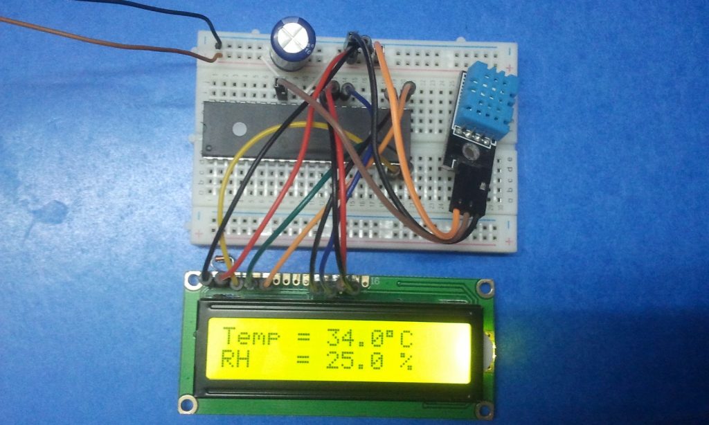
Interfacing DHTxx sensors with Microchip PIC microcontroller is so easy as what was done in the last project where PIC16F887 microcontroller is used to read relative humidity and temperature data from DHT11 sensor. Now this topic shows how to interface the PIC16F887 microcontroller with DHT22 sensor with mikroC Pro for PIC compiler.
Related Projects:
Interfacing PIC MCU with DHT11 sensor – mikroC
PIC16F887 Microcontroller with DHT22 digital sensor – CCS C
Hardware Required:
- PIC16F887 microcontroller
- DHT22 sensor (AM2302 – RHT03) — datasheet
- 16×2 LCD screen
- 10k variable resistor (or potentiometer)
- 4.7k ohm resistor
- 5V Power source
- Breadboards
- Jumper wires
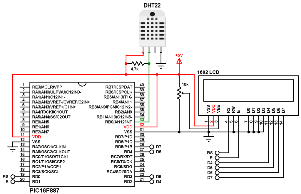
Interfacing PIC microcontroller with DHT22 (AM2302 – RHT03) sensor circuit:
Circuit diagram is shown below.
(All grounded terminals are connected together)
The DHT22 sensor has 4 pins connected to the circuit as (from left to right):
VCC pin connected to +5V,
Data pin connected to PIC16F887 microcontroller RB0 pin (#33),
Not connected pin,
GND pin connected to circuit ground.
The 1602 LCD screen (2 rows and 16 columns) is used to display temperature (in °C) and relative humidity values (in %), it is connected to the PIC16F887 MCU as follows:
RS —> pin RD0
E —> pin RD1
D4 —> pin RD2
D5 —> pin RD3
D6 —> pin RD4
D7 —> pin RD5
VSS, RW, D0, D1, D2, D3, and K are connected to circuit ground
VEE to the variable resistor (or potentiometer) output
VDD to +5V and A to +5V through 330 ohm resistor.
VEE pin is used to control the contrast of the LCD. A (anode) and K (cathode) are the back light LED pins.
In this example the PIC16F887 microcontroller runs with its internal oscillator (@ 8MHz) and MCLR pin is configured as digital input pin.
Interfacing PIC microcontroller with DHT22 sensor mikroC code:
mikroC configuration words are:
CONFIG1 : 0x2CD4
CONFIG2 : 0x0700
The configuration words can be changed from: Project –> Edit Project …
Functions used in the code:
void Start_Signal(void): used to send start signal to the DHT22 sensor.
unsigned short Check_Response(): used to detect the response signal which comes from the DHT22 sensor, this function returns 1 if OK and 0 if error.
unsigned short Read_Data(unsigned short* dht_data): this function reads 1 byte (8 bits) from the sensor, data are saved in the variable dht_data. Returns 0 if OK and 1 if error (time out error).
Rest of code is described through comments.
1 2 3 4 5 6 7 8 9 10 11 12 13 14 15 16 17 18 19 20 21 22 23 24 25 26 27 28 29 30 31 32 33 34 35 36 37 38 39 40 41 42 43 44 45 46 47 48 49 50 51 52 53 54 55 56 57 58 59 60 61 62 63 64 65 66 67 68 69 70 71 72 73 74 75 76 77 78 79 80 81 82 83 84 85 86 87 88 89 90 91 92 93 94 95 96 97 98 99 100 101 102 103 104 105 106 107 108 109 110 111 112 113 114 115 116 117 118 119 120 121 122 123 124 125 126 127 128 129 130 131 132 133 134 135 136 137 138 139 140 141 142 143 144 145 146 147 148 149 150 151 152 | /************************************************************************************** Interfacing DHT22 (AM2302 - RHT03) sensor with PIC16F887 microcontroller. C Code for mikroC PRO for PIC compiler Internal oscillator used @ 8MHz Configuration words: CONFIG1 = 0x2CD4 CONFIG2 = 0x0700 This is a free software with NO WARRANTY. http://simple-circuit.com/ ***************************************************************************************/ // LCD module connections sbit LCD_RS at RD0_bit; sbit LCD_EN at RD1_bit; sbit LCD_D4 at RD2_bit; sbit LCD_D5 at RD3_bit; sbit LCD_D6 at RD4_bit; sbit LCD_D7 at RD5_bit; sbit LCD_RS_Direction at TRISD0_bit; sbit LCD_EN_Direction at TRISD1_bit; sbit LCD_D4_Direction at TRISD2_bit; sbit LCD_D5_Direction at TRISD3_bit; sbit LCD_D6_Direction at TRISD4_bit; sbit LCD_D7_Direction at TRISD5_bit; // end LCD module connections // DHT22 sensor connection (here sensor data pin is connected to pin RB0) sbit DHT22_PIN at RB0_bit; sbit DHT22_PIN_Direction at TRISB0_bit; // End DHT11 sensor connection char temperature[] = "Temp = 00.0 C "; char humidity[] = "RH = 00.0 % "; unsigned short T_byte1, T_byte2, RH_byte1, RH_byte2, CheckSum ; unsigned int Temp, RH; void Start_Signal(void) { DHT22_PIN_Direction = 0; // Configure connection pin as output DHT22_PIN = 0; // Connection pin output low delay_ms(25); // Wait 25 ms DHT22_PIN = 1; // Connection pin output high delay_us(25); // Wait 25 us DHT22_PIN_Direction = 1; // Configure connection pin as input } unsigned short Check_Response() { TMR1H = 0; // Reset Timer1 TMR1L = 0; TMR1ON_bit = 1; // Enable Timer1 module while(!DHT22_PIN && TMR1L < 100); // Wait until DHT11_PIN becomes high (checking of 80µs low time response) if(TMR1L > 99) // If response time > 99µS ==> Response error return 0; // Return 0 (Device has a problem with response) else { TMR1H = 0; // Reset Timer1 TMR1L = 0; while(DHT22_PIN && TMR1L < 100); // Wait until DHT11_PIN becomes low (checking of 80µs high time response) if(TMR1L > 99) // If response time > 99µS ==> Response error return 0; // Return 0 (Device has a problem with response) else return 1; // Return 1 (response OK) } } unsigned short Read_Data(unsigned short* dht_data) { short i; *dht_data = 0; for(i = 0; i < 8; i++){ TMR1H = 0; // Reset Timer1 TMR1L = 0; while(!DHT22_PIN) // Wait until DHT11_PIN becomes high if(TMR1L > 100) { // If low time > 100 ==> Time out error (Normally it takes 50µs) return 1; } TMR1H = 0; // Reset Timer1 TMR1L = 0; while(DHT22_PIN) // Wait until DHT11_PIN becomes low if(TMR1L > 100) { // If high time > 100 ==> Time out error (Normally it takes 26-28µs for 0 and 70µs for 1) return 1; // Return 1 (timeout error) } if(TMR1L > 50) // If high time > 50 ==> Sensor sent 1 *dht_data |= (1 << (7 - i)); // Set bit (7 - i) } return 0; // Return 0 (data read OK) } void main() { OSCCON = 0X70; // Set internal oscillator to 8 MHz ANSELH = 0; // Configure all PORTB pins as digital T1CON = 0x10; // Set Timer1 clock source to internal with 1:2 prescaler (Timer1 clock = 1 MHz) TMR1H = 0; // Reset Timer1 TMR1L = 0; Lcd_Init(); // Initialize LCD module Lcd_Cmd(_LCD_CURSOR_OFF); // cursor off Lcd_Cmd(_LCD_CLEAR); // clear LCD while(1) { Start_Signal(); // Send start signal to the sensor if(Check_Response()) { // Check if there is a response from sensor (If OK start reading humidity and temperature data) // Read (and save) data from the DHT11 sensor and check time out errors if(Read_Data(&RH_byte1) || Read_Data(&RH_byte2) || Read_Data(&T_byte1) || Read_Data(&T_byte2) || Read_Data(&Checksum)) { Lcd_Cmd(_LCD_CLEAR); // clear LCD lcd_out(1, 5, "Time out!"); // Display "Time out!" } else { // If there is no time out error if(CheckSum == ((RH_Byte1 + RH_Byte2 + T_Byte1 + T_Byte2) & 0xFF)) { // If there is no checksum error RH = RH_byte1; RH = (RH << 8) | RH_byte2; Temp = T_byte1; Temp = (Temp << 8) | T_byte2; if (Temp > 0X8000){ temperature[6] = '-'; Temp = Temp & 0X7FFF; } else temperature[6] = ' '; temperature[7] = (Temp / 100) % 10 + 48; temperature[8] = (Temp / 10) % 10 + 48; temperature[10] = Temp % 10 + 48; if(RH == 1000) // If the relative humidity = 100.0 % humidity[6] = 1 + 48; // Put 1 of hundreds else humidity[6] = ' '; // Put space ' ' humidity[7] = (RH / 100) % 10 + 48; humidity[8] = (RH / 10) % 10 + 48; humidity[10] = RH % 10 + 48; temperature[11] = 223; // Put degree symbol (°) lcd_out(1, 1, temperature); lcd_out(2, 1, humidity); } // If there is a checksum error else { Lcd_Cmd(_LCD_CLEAR); // clear LCD lcd_out(1, 1, "Checksum Error!"); } } } // If there is a response (from the sensor) problem else { Lcd_Cmd(_LCD_CLEAR); // clear LCD lcd_out(1, 3, "No response"); lcd_out(2, 1, "from the sensor"); } TMR1ON_bit = 0; // Disable Timer1 module delay_ms(1000); // Wait 1 second } } // End of code |
The video below shows a Proteus simulation of the project:
Discover more from Simple Circuit
Subscribe to get the latest posts sent to your email.


does this code work on microC
would you mind giving an explanation to the timer calculations?
why TMR1L should reach 100?
I have the same problem and not only with this exercise but also with other tutorials, I looked online some other they are much better
hi
could you help me please, i apply every steps but still showing ”No response from the sensor” and i try try try to solve this issue but still same error
Change RB0_bit to RA0_bit
Change TRISB0_bit to TRISA0_bit
And connect the DHT22 to the appropriate PORTS pins.
You’ll also need to change ANSELH = 0 to reference PORTA, you can find the correct code statement in the PIC datasheet.
Hi,
Please how to configure Dht22 on PortA