This tutorial shows how to build a simple weather station using ESP8266 NodeMCU board (ESP12-E module) and BME280 barometric pressure, temperature & humidity sensor.
The NodeMCU microcontroller (ESP8266EX) reads temperature & humidity & pressure values from the BME280 sensor and prints them (respectively in °C & RH% & hPa) on ST7789 TFT display.
The ST7789 TFT module contains a display controller with the same name: ST7789. It’s a color display that uses SPI interface protocol and requires 3, 4 or 5 control pins, it’s low cost and easy to use. This display is an IPS display, it comes in different sizes (1.3″, 1.54″ …) but all of them should have the same resolution of 240×240 pixel, this means it has 57600 pixels. This module works with 3.3V only and it does not support 5V.
TFT: Thin-Film Transistor.
SPI: Serial Peripheral Interface.
IPS: In-Plane Switching.
To see how to interface the ESP8266 NodeMCU board with ST7789 TFT display, visit this post:
Interfacing ESP8266 NodeMCU with ST7789 TFT Display
About the BME280 sensor:
The BME280 sensor from Bosch Sensortec is a low cost digital pressure, temperature and humidity sensor with good accuracy. Because pressure changes with altitude we can use it as an altimeter with ±1 meter accuracy (pressure accuracy = ±1 hPa). Some parameters of the sensor are listed below:
Pressure range: 300 … 1100 hPa (equivalent to +9000…-500m above/below sea level)
Pressure resolution: 0.01 hPa ( < 10 cm)
Temperature range: -40 … 85 °C
Temperature resolution: 0.01 °C
Humidity range: 0 … 100 %
Interface: I2C and SPI
Supply voltage range: 1.71 … 3.6 V
In this project the BME280 sensor is used in I2C mode.
Hardware Required:
- ESP8266 NodeMCU board
- ST7789 TFT display module
- BME280 sensor module —-> datasheet
- micro USB cable (for programming and powering the circuit)
- Breadboard
- Jumper wires
ESP8266 NodeMCU with BME280 sensor and ST7789 TFT circuit:
Project circuit schematic diagram is shown below.
Generally, the BME280 sensor module has at least 4 pins because it can work in SPI mode or I2C mode, it’s connected to the ESP8266 NodeMCU board as described below.
For the I2C mode we need 4 pins: VCC, GND, SDA and SCL where:
VCC is the supply pin which is connected to NodeMCU 3V3 pin,
GND (ground) is connected to NodeMCU GND pin,
SDA is I2C bus serial data line, connected to NodeMCU pin D2 (GPIO4),
SCL is I2C bus serial clock line, connected to NodeMCU pin D1 (GPIO5).
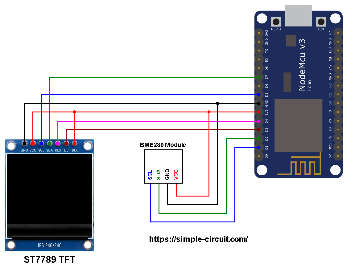
The ST7789 display module shown in project circuit diagram has 7 pins: (from right to left): GND (ground), VCC, SCL (serial clock), SDA (serial data), RES (reset), DC (or D/C: data/command) and BLK (back light).
The ST7789 TFT display module is connected to the NodeMCU board as follows:
GND is connected to pin GND of the NodeMCU board,
VCC and BL are connected to pin 3V3,
SCL pin is connected to D5 (ESP8266EX GPIO14),
SDA pin is connected to D7 (ESP8266EX GPIO13),
RES pin is connected to D4 (ESP8266EX GPIO2),
DC pin is connected to D3 (ESP8266EX GPIO0).
If the display module has a CS pin (Chip Select) then it should be connected to NodeMCU pin D8 (GPIO15).
Connecting the BLK pin is optional. The back light turns off when the BLK pin connected to the ground (GND).
Pins D5 (GPIO14) and D7 (GPIO13) are hardware SPI module pins of the ESP8266EX microcontroller respectively for SCK (serial clock) and MOSI (master-out slave-in).
ESP8266 NodeMCU with BME280 sensor and ST7789 TFT code:
The following Arduino code requires 3 libraries from Adafruit Industries:
The first library is a driver for the ST7789 TFT display which can be installed from Arduino IDE library manager (Sketch —> Include Library —> Manage Libraries …, in the search box write “st7789” and install the one from Adafruit).
The second library is Adafruit graphics library which can be installed also from Arduino IDE library manager.
The 3rd library is for the BME280 sensor, it may be installed using library manager (in the search box write “bme280” and choose the one from Adafruit).
The 3 libraries can be installed manually, first download them from the following links:
Adafruit ST7789 TFT library —-> direct link
Adafruit graphics library —-> direct link
Adafruit BME280 Library —-> direct link
You may need to install Adafruit Unified Sensor library if it’s not already installed, download link is below:
Adafruit Unified Sensor library —-> direct link
After the download, go to Arduino IDE —> Sketch —> Include Library —> Add .ZIP Library … and browse for the .zip file (previously downloaded).
The same thing for the other library files.
Hints:
In the code there are total of 4 libraries, they’re included in the code as follows:
1 2 3 4 | #include <Wire.h> // Wire library (required for I2C devices) #include <Adafruit_GFX.h> // Adafruit core graphics library #include <Adafruit_ST7789.h> // Adafruit hardware-specific library for ST7789 #include <Adafruit_BME280.h> // Adafruit BME280 sensor library |
The connection of the ST7789 TFT display with the NodeMCU board is as shown below where the display is connected to hardware SPI module of the NodeMCU (pins: SCK and MOSI):
1 2 3 4 5 6 7 8 | // ST7789 TFT module connections #define TFT_DC D3 // TFT DC pin is connected to NodeMCU pin D3 (GPIO0) #define TFT_RST D4 // TFT RST pin is connected to NodeMCU pin D4 (GPIO2) #define TFT_CS D8 // TFT CS pin is connected to NodeMCU pin D8 (GPIO15) // initialize ST7789 TFT library with hardware SPI module // SCK (CLK) ---> NodeMCU pin D5 (GPIO14) // MOSI(DIN) ---> NodeMCU pin D7 (GPIO13) Adafruit_ST7789 tft = Adafruit_ST7789(TFT_CS, TFT_DC, TFT_RST); |
And the TFT display is initialized using the following command:
1 2 | // if the display has CS pin try with SPI_MODE0 tft.init(240, 240, SPI_MODE2); // init ST7789 display 240x240 pixel |
As any other I2C device, the BME280 sensor has an I2C slave address which may be 0x76 or 0x77. This address depends on the connection of the SDO pin (used for SPI mode as serial data out or MISO), if the SDO pin is connected (directly or through resistor) to VCC (3.3V) the address will be 0x77, and if it’s connected to GND the address will be 0x76.
The default I2C address of the BME280 library is defined as 0x77 and my device I2C address is 0x76.
In the code, the definition of the I2C slave address and the initialization of its library are shown below:
1 2 3 4 | // define device I2C address: 0x76 or 0x77 (0x77 is library default address) #define BME280_I2C_ADDRESS 0x76 // initialize Adafruit BME280 library Adafruit_BME280 bme280; |
The initialization of the BME280 sensor is done using the function begin() which returns 1 if OK and 0 if error. In the code the initialization with the previously defined address is as shown below:
1 | bme280.begin(BME280_I2C_ADDRESS) |
Reading the values of temperature and pressure:
1 2 3 4 | // read temperature, humidity and pressure from the BME280 sensor float temp = bme280.readTemperature(); // get temperature in °C float humi = bme280.readHumidity(); // get humidity in % float pres = bme280.readPressure(); // get pressure in Pa |
Note that the BME280 sensor library returns the value of the pressure in Pa unit and to convert it to hPa we’ve to divide it by 100.
1 bar = 10000 Pa = 100 hPa. ( 1 hPa = 100 Pa = 1 millibar)
Pa: Pascal
hPa: hectoPascal
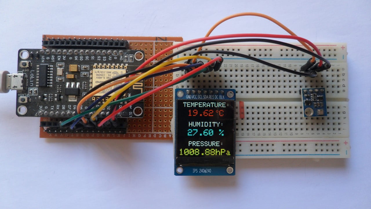
Temperature, humidity and pressure values are printed on the ST7789 TFT display.
If there is a problem with the BME280 sensor (for example wrong device address) the screen will display Connection Error
Full Arduino Code:
1 2 3 4 5 6 7 8 9 10 11 12 13 14 15 16 17 18 19 20 21 22 23 24 25 26 27 28 29 30 31 32 33 34 35 36 37 38 39 40 41 42 43 44 45 46 47 48 49 50 51 52 53 54 55 56 57 58 59 60 61 62 63 64 65 66 67 68 69 70 71 72 73 74 75 76 77 78 79 80 81 82 83 84 85 86 87 88 89 90 91 92 93 94 95 96 97 98 99 100 101 102 103 | /************************************************************************ * * ESP8266 NodeMCU Interface with ST7789 TFT display (240x240 pixel) and * BME280 barometric pressure & temperature & humidity sensor. * This is a free software with NO WARRANTY. * https://simple-circuit.com/ * ************************************************************************/ #include <Wire.h> // Wire library (required for I2C devices) #include <Adafruit_GFX.h> // Adafruit core graphics library #include <Adafruit_ST7789.h> // Adafruit hardware-specific library for ST7789 #include <Adafruit_BME280.h> // Adafruit BME280 sensor library // ST7789 TFT module connections #define TFT_DC D3 // TFT DC pin is connected to NodeMCU pin D3 (GPIO0) #define TFT_RST D4 // TFT RST pin is connected to NodeMCU pin D4 (GPIO2) #define TFT_CS D8 // TFT CS pin is connected to NodeMCU pin D8 (GPIO15) // initialize ST7789 TFT library with hardware SPI module // SCK (CLK) ---> NodeMCU pin D5 (GPIO14) // MOSI(DIN) ---> NodeMCU pin D7 (GPIO13) Adafruit_ST7789 tft = Adafruit_ST7789(TFT_CS, TFT_DC, TFT_RST); // define device I2C address: 0x76 or 0x77 (0x77 is library default address) #define BME280_I2C_ADDRESS 0x76 // initialize Adafruit BME280 library Adafruit_BME280 bme280; void setup(void) { // initialize the ST7789 display (240x240 pixel) // if the display has CS pin try with SPI_MODE0 tft.init(240, 240, SPI_MODE2); // if the screen is flipped, remove this command tft.setRotation(2); // fill the screen with black color tft.fillScreen(ST77XX_BLACK); tft.setTextWrap(false); // turn off text wrap option // initialize the BME280 sensor Wire.begin(D2, D1); // set I2C pins [SDA = D2, SCL = D1], default clock is 100kHz if( bme280.begin(BME280_I2C_ADDRESS) == 0 ) { // connection error or device address wrong! tft.setTextColor(ST77XX_WHITE, ST77XX_BLACK); // set text color to white and black background tft.setTextSize(4); // text size = 4 tft.setCursor(3, 88); // move cursor to position (3, 88) pixel tft.print("Connection"); tft.setCursor(63, 126); // move cursor to position (63, 126) pixel tft.print("Error"); while(1) delay(1000); // stay here } tft.setTextColor(ST77XX_WHITE, ST77XX_BLACK); // set text color to green and black background tft.setTextSize(3); // text size = 3 tft.setCursor(17, 0); // move cursor to position (17, 31) pixel tft.print("TEMPERATURE:"); tft.setCursor(44, 89); // move cursor to position (44, 140) pixel tft.print("HUMIDITY:"); tft.setCursor(44, 178); // move cursor to position (44, 140) pixel tft.print("PRESSURE:"); tft.setTextSize(4); // text size = 4 // print "°C" tft.drawCircle(173, 40, 4, ST77XX_RED); tft.drawCircle(173, 40, 5, ST77XX_RED); tft.setTextColor(ST77XX_RED, ST77XX_BLACK); // set text color to yellow and black background tft.setCursor(183, 34); tft.print("C"); } // main loop void loop() { delay(1000); // wait a second // read temperature, humidity and pressure from the BME280 sensor float temp = bme280.readTemperature(); // get temperature in °C float humi = bme280.readHumidity(); // get humidity in % float pres = bme280.readPressure(); // get pressure in Pa // print data on the display // 1: print temperature (in °C) tft.setTextColor(ST77XX_RED, ST77XX_BLACK); // set text color to yellow and black background tft.setCursor(15, 34); if(temp < 0) // if temperature < 0 tft.printf( "-%02u.%02u", (int)abs(temp), (int)(abs(temp) * 100) % 100 ); else // temperature >= 0 tft.printf( " %02u.%02u", (int)temp, (int)(temp * 100) % 100 ); // 2: print humidity tft.setTextColor(ST77XX_CYAN, ST77XX_BLACK); // set text color to cyan and black background tft.setCursor(39, 123); tft.printf( "%02u.%02u %%", (int)humi, (int)(humi * 100) % 100 ); // 3: print pressure (in hPa) tft.setTextColor(ST77XX_YELLOW, ST77XX_BLACK); // set text color to yellow and black background tft.setCursor(0, 212); tft.printf( "%04u.%02uhPa", (int)(pres/100), (int)((uint32_t)pres % 100) ); } // end of code. |
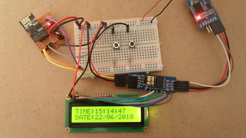
The picture below shows my simple protoboard circuit:
Discover more from Simple Circuit
Subscribe to get the latest posts sent to your email.

I have bought the various components and installed the code. Works like a charm! now I try to adapt it to my needs. Excellent work, thank you.
I like this tutorial. I would like to know how to change temperature to degrees F, and pressure to mmHg, as I live in the United States of America and do not use metric.