This post shows how to generate VGA signal using PIC18F46K22 8-bit microcontroller.
In this example the PIC18F46K22 MCU is used to draw shapes (lines, circles …) and print texts on a VGA monitor with black and white colors.
VGA: Video Graphics Array
Hardware required:
- PIC18F46K22 microcontroller —> datasheet
- VGA monitor
- 2 x 68 ohm resistor
- 220 ohm resistor
- VGA connector
- 5V source
- Breadboard
- Jumper wires
- PIC microcontroller programmer (PICkit 3, PICkit 4…)

Interfacing PIC18F46K22 MCU with VGA monitor circuit:
Example circuit diagram is shown below.
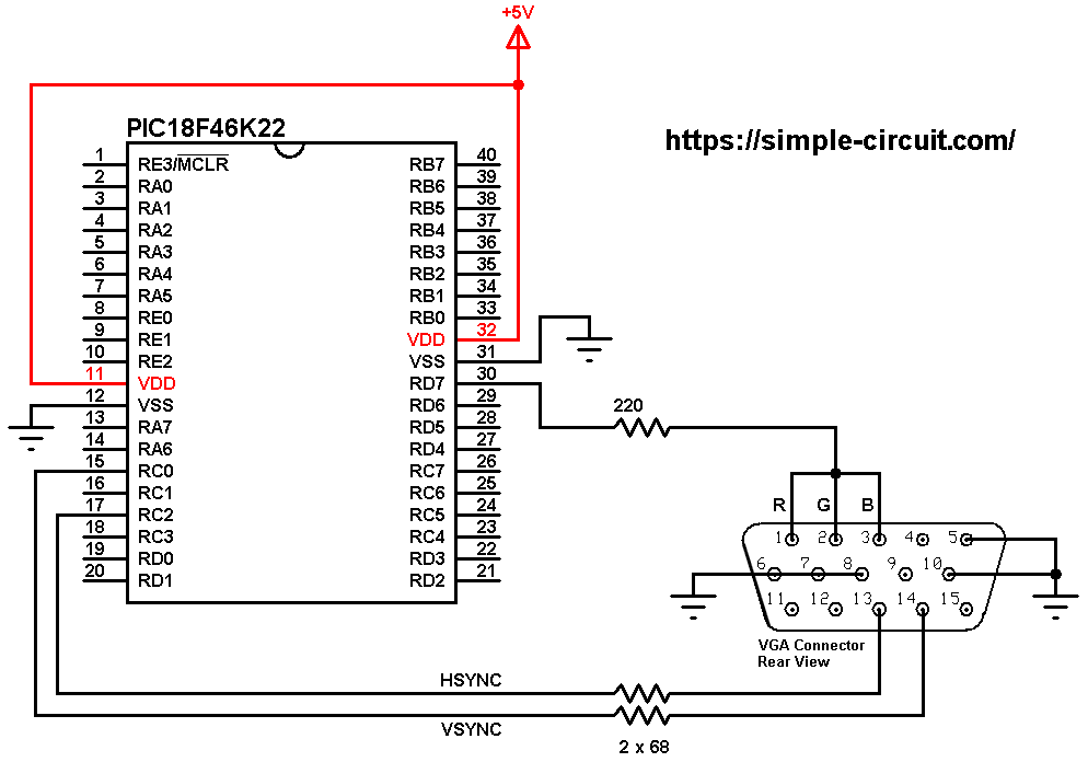
All the grounded terminals are connected together, don’t forget the negative of the 5V source!
HSYNC (horizontal synchronization) pin of the VGA connector (pin #13) is connected to PIC18F46K22 microcontroller pin RC2 (#17) through 68 ohm resistor.
VSYNC (vertical synchronization) pin of the VGA connector (#14) is connected to PIC18F46K22 microcontroller pin RC0 (#15) through 68 ohm resistor.
Color pins (R: red, G: green, B: blue) of the VGA connector (respectively #1, #2 and #3) are connected together in order to get white and black colors, they are connected to PIC18F46K22 microcontroller pin RD7 (#30) through 220 ohm resistor.
In this project the PIC18F46K22 microcontroller runs with its internal oscillator @ 64 MHz (16 MIPS), MCLR pin is configured as input.
Interfacing PIC18F46K22 MCU with VGA monitor code:
The C code below is for CCS C compiler, it was tested with version 5.083.
The following CCS C code requires two libraries:
The first library is a simple and small library for generating the required VGA signals (VSYNC, HSYNC and video).
The HSYNC (horizontal synchronization) signal is generated on pin RC2 (fixed).
The VSYNC (vertical synchronization) signal is generated on pin RC0 (default), other pin may be used.
The video signal is generated on pin RD7 (fixed).
Timer2 Module is configured to generate an interrupt every 31.75 microseconds (31.25 kHz), the horizontal synchronous pulses are generated as a PWM signal with frequency of 31.496 kHz. Within this interrupt the PIC18F46K22 outputs vertical synchronization pulse and video signal.
So, to get a PWM signal of 31.496 kHz, CCP1 module is configured to work in PWM mode using Timer2 module where the duty cycle is set to 88%. You can find this setting with comments in function named VGA_begin().
The VGA display has total of 525 lines, the VSYNC signal is generated with frequency of about 60Hz (31.25 kHz/525) with duty cycle of about 99%.
Note that this library uses all latch D register (PORTD), so connecting another device to PORTD may give some wrong results, but pins RD0~6 may still be used as inputs!
The actual displayed width of the VGA display is fixed to 160 pixel and the height may be: 64, 96, 128 or 160 pixel where the default height is 64 pixel.
The VGA library is configured to work with microcontroller frequency of 64MHz (16 MIPS) and PIC18F46K22.
An image of the display is stored in the microcontroller RAM space as a buffer (vga_buffer). The size of this buffer depends on the pre-defined height of the display (default is 160×64/8 = .1280).
The default VGA buffer is filled with an image (house) as shown in the above picture, I got it from MikroElektronika!
The VGA library is designed to work with graphics library which helps us to easily draw many shapes and write texts with different sizes. This library generates the video signal in 2 colors, connecting the three color pins of the VGA connector together as shown in the circuit diagram above will give black and white colors.
The VGA library download link is below, its full name (with extension) is VGA.c:
VGA Library for CCS C compiler
Graphics library full name is GFX_Library.c, download link is the one below:
Graphics library for CCS C compiler:
After the download of the 2 library files, add both of them to the project folder.
Rest of code is described through comments.
Full CCS C code:
1 2 3 4 5 6 7 8 9 10 11 12 13 14 15 16 17 18 19 20 21 22 23 24 25 26 27 28 29 30 31 32 33 34 35 36 37 38 39 40 41 42 43 44 45 46 47 48 49 50 51 52 53 54 55 56 57 58 59 60 61 62 63 64 65 66 67 68 69 70 71 72 73 74 75 76 77 78 79 80 81 82 83 84 85 86 87 88 89 90 91 92 93 94 95 96 97 98 99 100 101 102 103 104 105 106 107 108 109 110 111 112 113 114 115 116 117 118 119 120 121 122 123 124 125 126 127 128 129 130 131 132 133 134 135 136 137 138 139 140 141 142 143 144 145 146 147 148 149 150 151 152 153 154 155 156 157 158 159 160 161 162 163 164 165 166 167 168 169 170 171 172 173 174 175 176 177 178 179 180 181 182 183 184 185 186 187 188 189 190 191 192 193 194 195 196 197 198 199 200 201 202 203 204 205 206 207 208 209 210 211 212 213 214 215 216 217 218 219 220 221 222 223 224 225 226 227 228 229 230 231 232 233 234 235 236 237 238 239 240 241 242 243 244 245 246 247 248 249 250 251 252 253 254 255 256 257 258 259 260 261 262 263 264 265 266 267 268 269 270 271 272 273 274 275 276 277 278 279 280 281 282 283 284 285 286 287 288 289 290 291 292 293 294 295 296 297 | /************************************************************************** Interfacing PIC18F46K22 microcontroller with VGA monitor (160x64 pixel). Graphics test example. C Code for CCS C compiler. This is a free software with NO WARRANTY. https://simple-circuit.com/ /************************************************************************** Original code by Adafruit Industries ------> http://www.adafruit.com/ **************************************************************************/ // uncomment only one of the following if you want to use higher height pixel (default if 64) //#define VGAHEIGHT_96 //#define VGAHEIGHT_128 //#define VGAHEIGHT_160 // uncomment this line if you want to use VSYNC pin other than RC0 (for example RB2) //#define VSYNCPIN PIN_B2 #include <18F46K22.h> #fuses NOMCLR, NOLVP, NOBROWNOUT, PUT, NOXINST #use delay(internal = 64MHz) #use fast_io(c) #use fast_io(d) #include <VGA.c> // include VGA driver source code #include <GFX_Library.c> // include graphics library source code // define random max number #define RAND_MAX (display_width - 1) // include std library source code (required by rand() function) #include <stdlib.h> #define NUMFLAKES 10 #define XPOS 0 #define YPOS 1 #define DELTAY 2 #define LOGO16_GLCD_HEIGHT 16 #define LOGO16_GLCD_WIDTH 16 rom char logo16_glcd_bmp[] = { 0b00000000, 0b11000000, 0b00000001, 0b11000000, 0b00000001, 0b11000000, 0b00000011, 0b11100000, 0b11110011, 0b11100000, 0b11111110, 0b11111000, 0b01111110, 0b11111111, 0b00110011, 0b10011111, 0b00011111, 0b11111100, 0b00001101, 0b01110000, 0b00011011, 0b10100000, 0b00111111, 0b11100000, 0b00111111, 0b11110000, 0b01111100, 0b11110000, 0b01110000, 0b01110000, 0b00000000, 0b00110000 }; void testdrawbitmap(rom uint8_t *bitmap, uint8_t w, uint8_t h) { static uint8_t icons[NUMFLAKES][3], f, x_pos, y_pos; // initialize for (f=0; f< NUMFLAKES; f++) { icons[f][XPOS] = rand(); icons[f][YPOS] = 0; icons[f][DELTAY] = (rand() % 5) + 1; } icons[0][XPOS] = 30; while (TRUE) { uint8_t f; // draw each icon for (f=0; f< NUMFLAKES; f++) { x_pos = icons[f][XPOS]; y_pos = icons[f][YPOS]; display_drawBitmapV2(x_pos, y_pos, bitmap, w, h, WHITE); } delay_ms(200); // then erase it + move it for (f=0; f< NUMFLAKES; f++) { x_pos = icons[f][XPOS]; y_pos = icons[f][YPOS]; display_drawBitmapV2(x_pos, y_pos, bitmap, w, h, BLACK); // move it icons[f][YPOS] += icons[f][DELTAY]; // if its gone, reinit if (icons[f][YPOS] > display_height) { icons[f][XPOS] = rand(); icons[f][YPOS] = 0; icons[f][DELTAY] = (rand() % 5) + 1; } } } } void testdrawchar(void) { display_setTextSize(1); display_setTextColor(WHITE); display_setCursor(0, 0); for (uint8_t i=0; i < 168; i++) { if (i == '\n' || i == '\r') continue; display_print(i); } } void testdrawcircle(void) { for (int16_t i=0; i<display_height; i+=2) { display_drawCircle(display_width/2, display_height/2, i, WHITE); } } void testfillrect(void) { uint8_t color = 1; for (int16_t i=0; i<display_height/2; i+=3) { // alternate colors display_fillRect(i, i, display_width-i*2, display_height-i*2, color%2); color++; } } void testdrawtriangle(void) { for (int16_t i=0; i<min(display_width,display_height)/2; i+=5) { display_drawTriangle(display_width/2, display_height/2-i, display_width/2-i, display_height/2+i, display_width/2+i, display_height/2+i, WHITE); } } void testfilltriangle(void) { uint8_t color = WHITE; for (int16_t i=min(display_width,display_height)/2; i>0; i-=5) { display_fillTriangle(display_width/2, display_height/2-i, display_width/2-i, display_height/2+i, display_width/2+i, display_height/2+i, color); if (color == BLACK) color = WHITE; else color = BLACK; } } void testdrawroundrect(void) { for (int16_t i=0; i<display_height/2-2; i+=2) { display_drawRoundRect(i, i, display_width-2*i, display_height-2*i, display_height/4, WHITE); } } void testfillroundrect(void) { uint8_t color = WHITE; for (int16_t i=0; i<display_height/2-2; i+=2) { display_fillRoundRect(i, i, display_width-2*i, display_height-2*i, display_height/4, color); if (color == BLACK) color = WHITE; else color = BLACK; } } void testdrawrect(void) { for (int16_t i=0; i<display_height/2; i+=2) { display_drawRect(i, i, display_width-2*i, display_height-2*i, WHITE); } } void testdrawline() { int16_t i; for (i=0; i<display_width; i+=4) { display_drawLine(0, 0, i, display_height-1, WHITE); } for (i=0; i<display_height; i+=4) { display_drawLine(0, 0, display_width-1, i, WHITE); } delay_ms(250); display_clear(); for (i=0; i<display_width; i+=4) { display_drawLine(0, display_height-1, i, 0, WHITE); } for (i=display_height-1; i>=0; i-=4) { display_drawLine(0, display_height-1, display_width-1, i, WHITE); } delay_ms(250); display_clear(); for (i=display_width-1; i>=0; i-=4) { display_drawLine(display_width-1, display_height-1, i, 0, WHITE); } for (i=display_height-1; i>=0; i-=4) { display_drawLine(display_width-1, display_height-1, 0, i, WHITE); } delay_ms(250); display_clear(); for (i=0; i<display_height; i+=4) { display_drawLine(display_width-1, 0, 0, i, WHITE); } for (i=0; i<display_width; i+=4) { display_drawLine(display_width-1, 0, i, display_height-1, WHITE); } delay_ms(250); } // main function void main(void) { VGA_begin(); // VGA init delay_ms(10000); // wait 10 seconds display_clear(); // clears the screen and buffer // draw a single pixel display_drawPixel(10, 10, WHITE); delay_ms(2000); display_clear(); // draw many lines testdrawline(); delay_ms(2000); display_clear(); // draw rectangles testdrawrect(); delay_ms(2000); display_clear(); // draw multiple rectangles testfillrect(); delay_ms(2000); display_clear(); // draw mulitple circles testdrawcircle(); delay_ms(2000); display_clear(); // draw a circle, 10 pixel radius display_fillCircle(display_width/2, display_height/2, 10, WHITE); delay_ms(2000); display_clear(); testdrawroundrect(); delay_ms(2000); display_clear(); testfillroundrect(); delay_ms(2000); display_clear(); testdrawtriangle(); delay_ms(2000); display_clear(); testfilltriangle(); delay_ms(2000); display_clear(); // draw the first ~12 characters in the font testdrawchar(); delay_ms(2000); display_clear(); // text display tests display_setTextSize(1); display_setTextColor(WHITE); display_setCursor(0, 0); display_print("Hello, world!\r\n"); display_setTextColor(BLACK, WHITE); // 'inverted' text printf(display_print, "%f\r\n", 3.141592); display_setTextSize(2); display_setTextColor(WHITE); printf(display_print, "0x%LX\r\n", 0xDEADBEEF); delay_ms(2000); // rotation example display_clear(); display_setRotation(1); // rotate 90 degrees counter clockwise, can also use values of 2 and 3 to go further. display_setTextSize(1); display_setTextColor(WHITE); display_setCursor(0, 0); display_print("Rotation\r\n"); display_setTextSize(2); display_print("Example!\r\n"); delay_ms(2000); // revert back to no rotation display_setRotation(0); // miniature bitmap display display_clear(); display_drawBitmapV2(30, 16, logo16_glcd_bmp, 16, 16, WHITE); // draw a bitmap icon and 'animate' movement testdrawbitmap(logo16_glcd_bmp, LOGO16_GLCD_WIDTH, LOGO16_GLCD_HEIGHT); } // end of code. |
Interfacing PIC18F46K22 MCU with VGA monitor video:
The video below shows my breadboard test circuit:
Related Projects:
VGA Clock with PIC18F46K22 MCU and DS3231 RTC
Interfacing Arduino with VGA Monitor
Discover more from Simple Circuit
Subscribe to get the latest posts sent to your email.