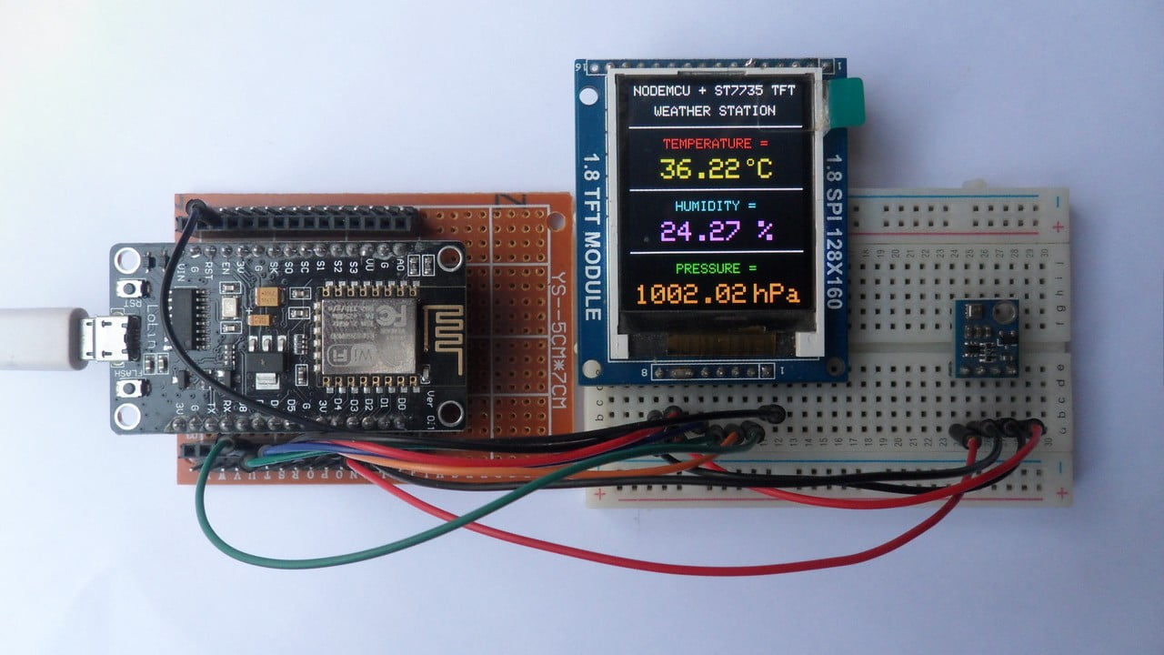
This tutorial shows how to build weather station using ESP8266 NodeMCU board (ESP12-E module) and BME280 barometric pressure, temperature & humidity sensor.
The NodeMCU microcontroller (ESP8266EX) reads temperature & humidity & pressure values from the BME280 sensor and prints them (respectively in °C & RH% & hPa) on ST7735 TFT display.
The ST7735 TFT is a color display which has a resolution of 128×160 pixel, it communicates with the master device using SPI protocol.
TFT: Thin-Film Transistor
SPI: Serial Peripheral Interface
To see how to interface the NodeMCU board with the ST7735 TFT display, visit this post:
Interfacing ESP8266 NodeMCU with ST7735 TFT
About the BME280 sensor:
The BME280 sensor from Bosch Sensortec is a low cost digital pressure, temperature and humidity sensor with good accuracy. Because pressure changes with altitude we can use it as an altimeter with ±1 meter accuracy (pressure accuracy = ±1 hPa). Some parameters of the sensor are listed below:
Pressure range: 300 … 1100 hPa (equivalent to +9000…-500m above/below sea level)
Pressure resolution: 0.01 hPa ( < 10 cm)
Temperature range: -40 … 85 °C
Temperature resolution: 0.01 °C
Humidity range: 0 … 100 %
Interface: I2C and SPI
Supply voltage range: 1.71 … 3.6 V
In this project the BME280 sensor is used in I2C mode.
Hardware Required:
- ESP8266 NodeMCU board
- ST7735 TFT display module
- BME280 sensor module —-> datasheet
- micro USB cable (for programming and powering the circuit)
- Breadboard
- Jumper wires
NodeMCU with BME280 sensor and ST7735 TFT circuit:
Project circuit schematic diagram is shown below.
The ST7735S shown in project circuit diagram has 8 pins: (from right to left): RST (reset), CE (chip enable), DC (or D/C: data/command), DIN (data in), CLK (clock), VCC, BL (back light) and Gnd (ground).

The ST7735 TFT display is connected to the NodeMCU board as follows:
RST pin is connected to NodeMCU reset pin (RST),
CS pin is connected to D8 (ESP8266EX GPIO15),
D/C pin is connected to D4 (ESP8266EX GPIO2),
DIN (MOSI) pin is connected to D7 (ESP8266EX GPIO13),
CLK (SCK) pin is connected to D5 (ESP8266EX GPIO14),
VCC and BL are connected to pin 3V3,
GND is connected to pin GND of the NodeMCU board.
Pins D5 (GPIO14), D7 (GPIO13) and D8 (GPIO15) are hardware SPI module pins of the ESP8266EX microcontroller respectively for SCK (serial clock), MOSI (master-out slave-in) and CS (chip select).
Generally, the BME280 sensor module has at least 4 pins because it can work in SPI mode or I2C mode. For the I2C mode we need 4 pins: VCC, GND, SDA and SCL where:
GND (ground) is connected to NodeMCU GND pin,
VCC is the supply pin which is connected to NodeMCU 3V3 pin,
SDA is I2C bus serial data line, connected to NodeMCU pin D3 (GPIO0),
SCL is I2C bus serial clock line, connected to NodeMCU pin D2 (GPIO4).
NodeMCU with BME280 sensor and ST7735 TFT code:
The following Arduino code requires 3 libraries from Adafruit Industries:
The first library is a driver for the ST7735 TFT display, download link is below:
Adafruit ST7735 TFT library —-> direct link
The 2nd library is Adafruit graphics library which can be downloaded from the following link
Adafruit graphics library —-> direct link
The third library is for the BME280 sensor:
Adafruit BME280 Library —-> direct link
You may need to install Adafruit Unified Sensor library if it’s not already installed, download link is below:
Adafruit Unified Sensor library —-> direct link
After the download, go to Arduino IDE —> Sketch —> Include Library —> Add .ZIP Library … and browse for the .zip file (previously downloaded).
The same thing for the other library files.
Hints:
In the code there are total of 4 libraries, they’re included in the code as follows:
1 2 3 4 | #include <Wire.h> // include Wire library (required for I2C devices) #include <Adafruit_GFX.h> // include Adafruit graphics library #include <Adafruit_ST7735.h> // include Adafruit ST7735 TFT library #include <Adafruit_BME280.h> // include Adafruit BME280 sensor library |
As any other I2C device, the BME280 sensor has an I2C slave address which may be 0x76 or 0x77. This address depends on the connection of the SDO pin (used for SPI mode as serial data out or MISO), if the SDO pin is connected (directly or through resistor) to VCC (3.3V) the address will be 0x77, and if it’s connected to GND the address will be 0x76.
The default I2C address of the BME280 library is defined as 0x77 and my device I2C address is 0x76.
In the code, the definition of the I2C slave address and the initialization of its library are shown below:
1 2 3 4 | // define device I2C address: 0x76 or 0x77 (0x77 is library default address) #define BME280_I2C_ADDRESS 0x76 // initialize Adafruit BME280 library Adafruit_BME280 bme280; |
The initialization of the BME280 sensor is done using the function begin() which returns 1 if OK and 0 if error. In the code the initialization with the previously defined address is as shown below:
1 | bme280.begin(BME280_I2C_ADDRESS) |
Reading the values of temperature and pressure:
1 2 3 4 | // read temperature, humidity and pressure from the BME280 sensor float temp = bme280.readTemperature(); // get temperature in °C float humi = bme280.readHumidity(); // get humidity in % float pres = bme280.readPressure(); // get pressure in Pa |
Note that the BME280 sensor library returns the value of the pressure in Pa unit and to convert it to hPa we’ve to divide it by 100.
1 bar = 10000 Pa = 100 hPa. ( 1 hPa = 100 Pa = 1 millibar)
Pa: Pascal
hPa: hectoPascal
Temperature, humidity and pressure values are printed on the ST7735 TFT display.
If there is a problem with the BME280 sensor (for example wrong device address) the screen will display Connection Error
Full Arduino Code:
1 2 3 4 5 6 7 8 9 10 11 12 13 14 15 16 17 18 19 20 21 22 23 24 25 26 27 28 29 30 31 32 33 34 35 36 37 38 39 40 41 42 43 44 45 46 47 48 49 50 51 52 53 54 55 56 57 58 59 60 61 62 63 64 65 66 67 68 69 70 71 72 73 74 75 76 77 78 79 80 81 82 83 84 85 86 87 88 89 90 91 92 93 94 95 96 97 98 99 100 101 102 103 104 105 106 107 108 109 | /************************************************************************** * * Interfacing ESP8266 NodeMCU with ST7735S TFT display (128x160 Pixel) * and BME280 barometric pressure, temperature & humidity sensor. * This is a free software with NO WARRANTY. * http://simple-circuit.com/ * *************************************************************************/ #include <Wire.h> // include Wire library (required for I2C devices) #include <Adafruit_GFX.h> // include Adafruit graphics library #include <Adafruit_ST7735.h> // include Adafruit ST7735 TFT library #include <Adafruit_BME280.h> // include Adafruit BME280 sensor library // ST7735 TFT module connections #define TFT_RST -1 // TFT RST pin is connected to NodeMCU reset pin #define TFT_CS D8 // TFT CS pin is connected to NodeMCU pin D8 (GPIO15) #define TFT_DC D4 // TFT DC pin is connected to NodeMCU pin D4 (GPIO2) // initialize ST7735 TFT library with hardware SPI module // SCK (CLK) ---> NodeMCU pin D5 (GPIO14) // MOSI(DIN) ---> NodeMCU pin D7 (GPIO13) Adafruit_ST7735 tft = Adafruit_ST7735(TFT_CS, TFT_DC, TFT_RST); // define device I2C address: 0x76 or 0x77 (0x77 is library default address) #define BME280_I2C_ADDRESS 0x76 // initialize Adafruit BME280 library Adafruit_BME280 bme280; void setup(void) { tft.initR(INITR_BLACKTAB); // initialize a ST7735S chip, black tab tft.fillScreen(ST7735_BLACK); // fill screen with black color tft.drawFastHLine(0, 30, tft.width(), ST7735_WHITE); // draw horizontal white line at position (0, 30) tft.setTextColor(ST7735_WHITE, ST7735_BLACK); // set text color to white and black background tft.setTextSize(1); // text size = 1 tft.setCursor(4, 0); // move cursor to position (4, 0) pixel tft.print("NODEMCU + ST7735 TFT"); tft.setCursor(19, 15); // move cursor to position (19, 15) pixel tft.print("WEATHER STATION"); // initialize the BME280 sensor Wire.begin(D3, D2); // set I2C pins [SDA = D3, SCL = D2], default clock is 100kHz if( bme280.begin(BME280_I2C_ADDRESS) == 0 ) { // connection error or device address wrong! tft.setTextColor(ST7735_RED, ST7735_BLACK); // set text color to red and black background tft.setTextSize(2); // text size = 2 tft.setCursor(5, 76); // move cursor to position (5, 76) pixel tft.print("Connection"); tft.setCursor(35, 100); // move cursor to position (35, 100) pixel tft.print("Error"); while(1) // stay here delay(1000); } tft.drawFastHLine(0, 76, tft.width(), ST7735_WHITE); // draw horizontal white line at position (0, 76) tft.drawFastHLine(0, 122, tft.width(), ST7735_WHITE); // draw horizontal white line at position (0, 122) tft.setTextColor(ST7735_RED, ST7735_BLACK); // set text color to red and black background tft.setCursor(25, 39); // move cursor to position (25, 39) pixel tft.print("TEMPERATURE ="); tft.setTextColor(ST7735_CYAN, ST7735_BLACK); // set text color to cyan and black background tft.setCursor(34, 85); // move cursor to position (34, 85) pixel tft.print("HUMIDITY ="); tft.setTextColor(ST7735_GREEN, ST7735_BLACK); // set text color to green and black background tft.setCursor(34, 131); // move cursor to position (34, 131) pixel tft.print("PRESSURE ="); tft.setTextSize(2); // text size = 2 // print °C tft.drawCircle(89, 56, 2, ST7735_YELLOW); // print degree symbol ( ° ) tft.setCursor(95, 54); // move cursor to position (95, 54) pixel tft.setTextColor(ST7735_YELLOW, ST7735_BLACK); // set text color to yellow and black background tft.print("C"); } // main loop void loop() { // read temperature, humidity and pressure from the BME280 sensor float temp = bme280.readTemperature(); // get temperature in °C float humi = bme280.readHumidity(); // get humidity in % float pres = bme280.readPressure(); // get pressure in Pa // print data on the display // print temperature (in °C) tft.setCursor(11, 54); tft.setTextColor(ST7735_YELLOW, ST7735_BLACK); // set text color to yellow and black background if(temp < 0) // if temperature < 0 tft.printf( "-%02u.%02u", (int)abs(temp), (int)(abs(temp) * 100) % 100 ); else // temperature >= 0 tft.printf( " %02u.%02u", (int)temp, (int)(temp * 100) % 100 ); // 2: print humidity tft.setCursor(23, 100); tft.setTextColor(ST7735_MAGENTA, ST7735_BLACK); // set text color to magenta and black background tft.printf( "%02u.%02u %%", (int)humi, (int)(humi * 100) % 100 ); // 3: print pressure (in hPa) tft.setCursor(3, 146); tft.setTextColor(0xFD00, ST7735_BLACK); // set text color to orange and black background tft.printf( "%04u.%02u", (int)(pres/100), (int)((uint32_t)pres % 100) ); tft.setCursor(91, 146); tft.print("hPa"); delay(1000); // wait a second } // end of code. |
Discover more from Simple Circuit
Subscribe to get the latest posts sent to your email.

Hello,
Your project interests me a lot, which is why I have just completed it. On the other hand I encounter a problem of reading the atmospheric pressure, with program line “tft.printf (“% 04u.% 02u “, (int) (pres / 100), (int) ((uint32_t) pres% 10) ); “does not work properly at least with me. The result is much lower than the local pressure, for example the current pressure in my region is 1023 hPa and I only have 0995.82 hPa on the display. I put a little offset “float pres = bme280.readPressure () +10.0; // get pressure in Pa” but that did not change anything. I also replaced BME280 sensor with another one but I still have the same problem.
Would you be able to help me, so I can finish this great montage.
Thank you so much.
Best regards
Jimmy
P.S. you will have noticed, I am French on the one hand and on the other hand I am not a programmer, thank you for your indulgence