This post shows how to interface ESP8266 NodeMCU development board (ESP12-E module) with ST7735 TFT display (128×160 pixel resolution).
The ST7735 TFT display is a color display that uses SPI protocol, it’s low cost and easy to use.
This module works with 3.3V only, connecting it directly to a 5V system will not work and may damage its controller circuit!
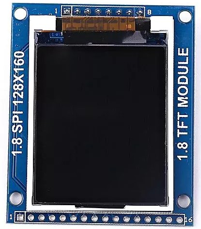
The display which is used in this project is shown below (face):
and the back of the display module:
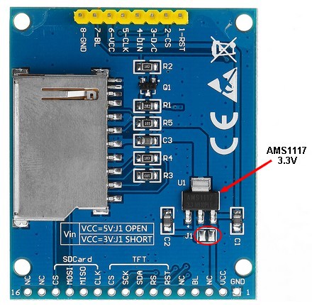
As shown in the back of the display module there is the AMS1117 3V3 voltage regulator, it’s used to supply the display controller circuit with 3.3V from an input supply of 5V (because it does work with 3.3V only).
Also, we can disuse the built-in voltage regulator (AMS1117 3V3) if we already have a regulated voltage source of 3.3V, here we should close (solder) jumper J1 (red ellipse).
Project Hardware Required:
- ESP8266 NodeMCU development board
- ST7735 TFT display module
- Breadboard
- Jumper wires

Interfacing NodeMCU with ST7735 TFT circuit:
Project circuit schematic diagram is shown below.
The ST7735S shown in project circuit diagram has 8 pins: (from right to left): RST (reset), CE (chip enable), DC (or D/C: data/command), DIN (data in), CLK (clock), VCC, BL (back light) and Gnd (ground).
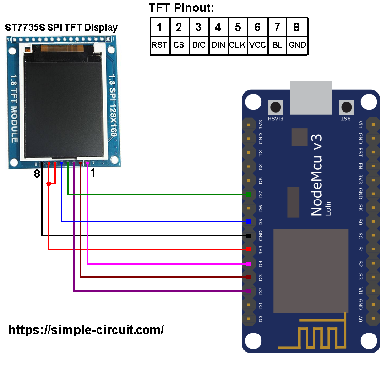
The ST7735 display is connected to the NodeMCU board as follows:
RST pin is connected to D4 (ESP8266EX GPIO2),
CS pin is connected to D3 (ESP8266EX GPIO0),
D/C pin is connected to D2 (ESP8266EX GPIO4),
DIN pin is connected to D7 (ESP8266EX GPIO13),
CLK pin is connected to D5 (ESP8266EX GPIO14),
VCC and BL are connected to pin 3V3,
GND is connected to pin GND of the NodeMCU board.
Pins D5 (GPIO14) and D7 (GPIO13) are hardware SPI module pins of the ESP8266EX microcontroller respectively for SCK (serial clock) and MOSI (master-out slave-in).
Interfacing NodeMCU with ST7735 TFT code:
The following Arduino code requires two libraries from Adafruit Industries:
The first library is a driver for the ST7735 TFT display which can be installed from Arduino IDE library manager (Sketch —> Include Library —> Manage Libraries …, in the search box write “st7735” and install the one from Adafruit).
The second library is Adafruit graphics library which can be installed also from Arduino IDE library manager.
Both libraries can be installed manually, first download them from the following 2 links:
Adafruit ST7735 TFT library —-> direct link
Adafruit graphics library —-> direct link
After the download, go to Arduino IDE —> Sketch —> Include Library —> Add .ZIP Library … and browse for the .zip file (previously downloaded).
The same thing for the other library file.
Arduino Code:
The Arduino code below is the Adafruit test example for the ST7735 display (comes with Adafruit ST7735 library) with few modifications in order to work with the circuit schematic shown above.
1 2 3 4 5 6 7 8 9 10 11 12 13 14 15 16 17 18 19 20 21 22 23 24 25 26 27 28 29 30 31 32 33 34 35 36 37 38 39 40 41 42 43 44 45 46 47 48 49 50 51 52 53 54 55 56 57 58 59 60 61 62 63 64 65 66 67 68 69 70 71 72 73 74 75 76 77 78 79 80 81 82 83 84 85 86 87 88 89 90 91 92 93 94 95 96 97 98 99 100 101 102 103 104 105 106 107 108 109 110 111 112 113 114 115 116 117 118 119 120 121 122 123 124 125 126 127 128 129 130 131 132 133 134 135 136 137 138 139 140 141 142 143 144 145 146 147 148 149 150 151 152 153 154 155 156 157 158 159 160 161 162 163 164 165 166 167 168 169 170 171 172 173 174 175 176 177 178 179 180 181 182 183 184 185 186 187 188 189 190 191 192 193 194 195 196 197 198 199 200 201 202 203 204 205 206 207 208 209 210 211 212 213 214 215 216 217 218 219 220 221 222 223 224 225 226 227 228 229 230 231 232 233 234 235 236 237 238 239 240 241 242 243 244 245 246 247 248 249 250 251 252 253 254 255 256 257 258 259 260 261 262 263 264 265 266 267 268 269 270 271 272 273 274 275 276 277 278 279 280 281 282 283 284 285 286 | /************************************************************************************** Interfacing ESP8266 NodeMCU with ST7735 TFT display (128x160 pixel). This is a free software with NO WARRANTY. http://simple-circuit.com/ /************************************************************************** This is a library for several Adafruit displays based on ST77* drivers. Works with the Adafruit 1.8" TFT Breakout w/SD card ----> http://www.adafruit.com/products/358 The 1.8" TFT shield ----> https://www.adafruit.com/product/802 The 1.44" TFT breakout ----> https://www.adafruit.com/product/2088 as well as Adafruit raw 1.8" TFT display ----> http://www.adafruit.com/products/618 Check out the links above for our tutorials and wiring diagrams. These displays use SPI to communicate, 4 or 5 pins are required to interface (RST is optional). Adafruit invests time and resources providing this open source code, please support Adafruit and open-source hardware by purchasing products from Adafruit! Written by Limor Fried/Ladyada for Adafruit Industries. MIT license, all text above must be included in any redistribution **************************************************************************/ #include <Adafruit_GFX.h> // include Adafruit graphics library #include <Adafruit_ST7735.h> // include Adafruit ST7735 TFT library // ST7735 TFT module connections #define TFT_RST D4 // TFT RST pin is connected to NodeMCU pin D4 (GPIO2) #define TFT_CS D3 // TFT CS pin is connected to NodeMCU pin D4 (GPIO0) #define TFT_DC D2 // TFT DC pin is connected to NodeMCU pin D4 (GPIO4) // initialize ST7735 TFT library with hardware SPI module // SCK (CLK) ---> NodeMCU pin D5 (GPIO14) // MOSI(DIN) ---> NodeMCU pin D7 (GPIO13) Adafruit_ST7735 tft = Adafruit_ST7735(TFT_CS, TFT_DC, TFT_RST); float p = 3.1415926; void setup(void) { tft.initR(INITR_BLACKTAB); // initialize a ST7735S chip, black tab uint16_t time = millis(); tft.fillScreen(ST7735_BLACK); time = millis() - time; delay(500); // large block of text tft.fillScreen(ST7735_BLACK); testdrawtext("Lorem ipsum dolor sit amet, consectetur adipiscing elit. Curabitur adipiscing ante sed nibh tincidunt feugiat. Maecenas enim massa, fringilla sed malesuada et, malesuada sit amet turpis. Sed porttitor neque ut ante pretium vitae malesuada nunc bibendum. Nullam aliquet ultrices massa eu hendrerit. Ut sed nisi lorem. In vestibulum purus a tortor imperdiet posuere. ", ST7735_WHITE); delay(1000); // tft print function! tftPrintTest(); delay(4000); // a single pixel tft.drawPixel(tft.width()/2, tft.height()/2, ST7735_GREEN); delay(500); // line draw test testlines(ST7735_YELLOW); delay(500); // optimized lines testfastlines(ST7735_RED, ST7735_BLUE); delay(500); testdrawrects(ST7735_GREEN); delay(500); testfillrects(ST7735_YELLOW, ST7735_MAGENTA); delay(500); tft.fillScreen(ST7735_BLACK); testfillcircles(10, ST7735_BLUE); testdrawcircles(10, ST7735_WHITE); delay(500); testroundrects(); delay(500); testtriangles(); delay(500); mediabuttons(); delay(500); delay(1000); } void loop() { tft.invertDisplay(true); delay(500); tft.invertDisplay(false); delay(500); } void testlines(uint16_t color) { tft.fillScreen(ST7735_BLACK); for (int16_t x=0; x < tft.width(); x+=6) { tft.drawLine(0, 0, x, tft.height()-1, color); } for (int16_t y=0; y < tft.height(); y+=6) { tft.drawLine(0, 0, tft.width()-1, y, color); } tft.fillScreen(ST7735_BLACK); for (int16_t x=0; x < tft.width(); x+=6) { tft.drawLine(tft.width()-1, 0, x, tft.height()-1, color); } for (int16_t y=0; y < tft.height(); y+=6) { tft.drawLine(tft.width()-1, 0, 0, y, color); } tft.fillScreen(ST7735_BLACK); for (int16_t x=0; x < tft.width(); x+=6) { tft.drawLine(0, tft.height()-1, x, 0, color); } for (int16_t y=0; y < tft.height(); y+=6) { tft.drawLine(0, tft.height()-1, tft.width()-1, y, color); } tft.fillScreen(ST7735_BLACK); for (int16_t x=0; x < tft.width(); x+=6) { tft.drawLine(tft.width()-1, tft.height()-1, x, 0, color); } for (int16_t y=0; y < tft.height(); y+=6) { tft.drawLine(tft.width()-1, tft.height()-1, 0, y, color); } } void testdrawtext(char *text, uint16_t color) { tft.setCursor(0, 0); tft.setTextColor(color); tft.setTextWrap(true); tft.print(text); } void testfastlines(uint16_t color1, uint16_t color2) { tft.fillScreen(ST7735_BLACK); for (int16_t y=0; y < tft.height(); y+=5) { tft.drawFastHLine(0, y, tft.width(), color1); } for (int16_t x=0; x < tft.width(); x+=5) { tft.drawFastVLine(x, 0, tft.height(), color2); } } void testdrawrects(uint16_t color) { tft.fillScreen(ST7735_BLACK); for (int16_t x=0; x < tft.width(); x+=6) { tft.drawRect(tft.width()/2 -x/2, tft.height()/2 -x/2 , x, x, color); } } void testfillrects(uint16_t color1, uint16_t color2) { tft.fillScreen(ST7735_BLACK); for (int16_t x=tft.width()-1; x > 6; x-=6) { tft.fillRect(tft.width()/2 -x/2, tft.height()/2 -x/2 , x, x, color1); tft.drawRect(tft.width()/2 -x/2, tft.height()/2 -x/2 , x, x, color2); } } void testfillcircles(uint8_t radius, uint16_t color) { for (int16_t x=radius; x < tft.width(); x+=radius*2) { for (int16_t y=radius; y < tft.height(); y+=radius*2) { tft.fillCircle(x, y, radius, color); } } } void testdrawcircles(uint8_t radius, uint16_t color) { for (int16_t x=0; x < tft.width()+radius; x+=radius*2) { for (int16_t y=0; y < tft.height()+radius; y+=radius*2) { tft.drawCircle(x, y, radius, color); } } } void testtriangles() { tft.fillScreen(ST7735_BLACK); int color = 0xF800; int t; int w = tft.width()/2; int x = tft.height()-1; int y = 0; int z = tft.width(); for(t = 0 ; t <= 15; t++) { tft.drawTriangle(w, y, y, x, z, x, color); x-=4; y+=4; z-=4; color+=100; } } void testroundrects() { tft.fillScreen(ST7735_BLACK); int color = 100; int i; int t; for(t = 0 ; t <= 4; t+=1) { int x = 0; int y = 0; int w = tft.width()-2; int h = tft.height()-2; for(i = 0 ; i <= 16; i+=1) { tft.drawRoundRect(x, y, w, h, 5, color); x+=2; y+=3; w-=4; h-=6; color+=1100; } color+=100; } } void tftPrintTest() { tft.setTextWrap(false); tft.fillScreen(ST7735_BLACK); tft.setCursor(0, 30); tft.setTextColor(ST7735_RED); tft.setTextSize(1); tft.println("Hello World!"); tft.setTextColor(ST7735_YELLOW); tft.setTextSize(2); tft.println("Hello World!"); tft.setTextColor(ST7735_GREEN); tft.setTextSize(3); tft.println("Hello World!"); tft.setTextColor(ST7735_BLUE); tft.setTextSize(4); tft.print(1234.567); delay(1500); tft.setCursor(0, 0); tft.fillScreen(ST7735_BLACK); tft.setTextColor(ST7735_WHITE); tft.setTextSize(0); tft.println("Hello World!"); tft.setTextSize(1); tft.setTextColor(ST7735_GREEN); tft.print(p, 6); tft.println(" Want pi?"); tft.println(" "); tft.print(8675309, HEX); // print 8,675,309 out in HEX! tft.println(" Print HEX!"); tft.println(" "); tft.setTextColor(ST7735_WHITE); tft.println("Sketch has been"); tft.println("running for: "); tft.setTextColor(ST7735_MAGENTA); tft.print(millis() / 1000); tft.setTextColor(ST7735_WHITE); tft.print(" seconds."); } void mediabuttons() { // play tft.fillScreen(ST7735_BLACK); tft.fillRoundRect(25, 10, 78, 60, 8, ST7735_WHITE); tft.fillTriangle(42, 20, 42, 60, 90, 40, ST7735_RED); delay(500); // pause tft.fillRoundRect(25, 90, 78, 60, 8, ST7735_WHITE); tft.fillRoundRect(39, 98, 20, 45, 5, ST7735_GREEN); tft.fillRoundRect(69, 98, 20, 45, 5, ST7735_GREEN); delay(500); // play color tft.fillTriangle(42, 20, 42, 60, 90, 40, ST7735_BLUE); delay(50); // pause color tft.fillRoundRect(39, 98, 20, 45, 5, ST7735_RED); tft.fillRoundRect(69, 98, 20, 45, 5, ST7735_RED); // play color tft.fillTriangle(42, 20, 42, 60, 90, 40, ST7735_GREEN); } // end of code. |
Project hardware circuit should give the same result as the one shown in the following video where Arduino UNO board is used (NodeMCU is much faster than Arduino UNO):
ESP8266 Projects with ST7735 TFT display:
NodeMCU with ST7735 TFT and LM35 Analog Temperature Sensor
ESP8266 NodeMCU Internet Clock with ST7735 TFT
ESP8266 NodeMCU with ST7735 TFT and DHT11 Sensor
Interfacing NodeMCU with DHT22 Sensor and ST7735 TFT
Interfacing NodeMCU with DS3231 RTC and ST7735 TFT
NodeMCU with ST7735 TFT and BMP280 Sensor
Interfacing NodeMCU with BME280 Sensor and ST7735 TFT
Discover more from Simple Circuit
Subscribe to get the latest posts sent to your email.

I am trying to get the graphicstest sketch to work in a small red ST7735 TFT Display when driven by a Lolin NodeMcu V3.0. The sketch compiles and uploads but no graphics appear. What am I doing wrong?