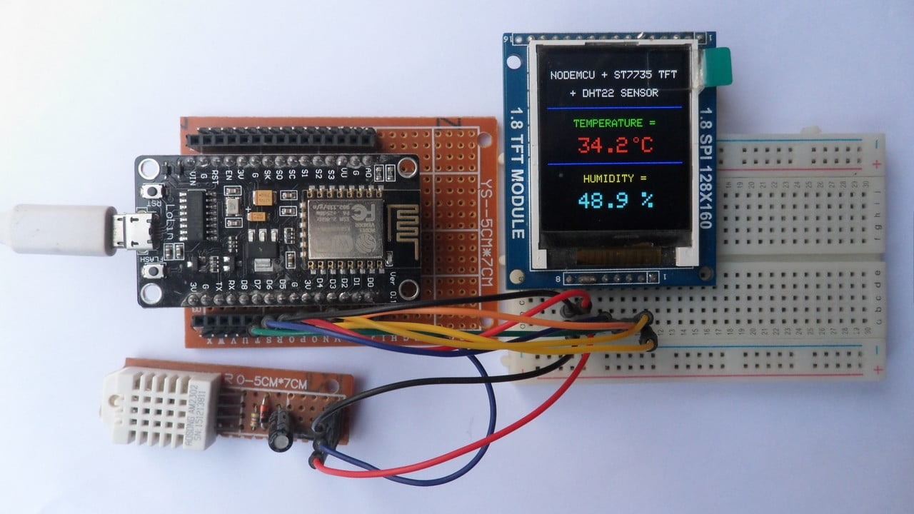
This post shows how to interface ESP8266 NodeMCU board (ESP-12E) with DHT22 (AM2302, RHT03) digital humidity and temperature sensor.
The NodeMCU microcontroller (ESP8266EX) reads temperature (in °C) & humidity (in rH%) values from the DHT22 sensor and print their values on ST7735 TFT display.
The ST7735 TFT used in this project is a color display which has a resolution of 128×160 pixel, it communicates with the master device using SPI protocol.
TFT: Thin-Film Transistor
SPI: Serial Peripheral Interface
To see how to interface the NodeMCU board with the ST7735 TFT display, visit this post:
Interfacing ESP8266 NodeMCU with ST7735 TFT
The DHT22 sensor has the following characteristics:
- Humidity Range: 0 ~ 100% RH
- Humidity Accuracy: ±2% RH (max ±5% RH)
- Temperature Range: -40 ~ 80 °C
- Temperature Accuracy: ±0.5 °C
- Operating Voltage: 3.3V ~ 5.5V
- Resolution = 0.1
Hardware Required:
- NodeMCU development board
- ST7735 TFT display module
- DHT22 (AM2302, RHT03) humidity and temperature sensor —-> datasheet
- 4.7k ohm resistor
- Micro USB cable (for programming and powering the whole circuit)
- Breadboard
- Jumper wires
NodeMCU with DHT22 sensor and ST7735 TFT display circuit:
Project circuit diagram is shown below.
The DHT22 sensor has 4 pins (from left to right):
Pin 1 is power supply pin, connected NodeMCU 3V3 pin,
Pin 2: data output pin, connected to NodeMCU digital pin 1 (D1),
Pin 3: not connected pin,
Pin 4: GND (ground), connected to NodeMCU GND pin.
A pull-up resistor of 4.7k ohm is required because the DHT22 sensor has an open drain output.
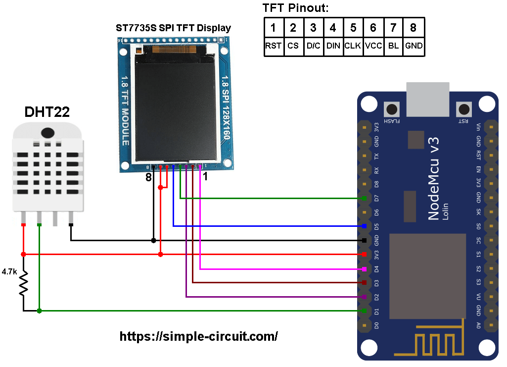
The ST7735S shown in project circuit diagram has 8 pins: (from right to left): RST (reset), CE (chip enable), DC (or D/C: data/command), DIN (data in), CLK (clock), VCC, BL (back light) and Gnd (ground).
The ST7735 display is connected to the NodeMCU board as follows:
RST pin is connected to D4 (ESP8266EX GPIO2),
CS pin is connected to D3 (ESP8266EX GPIO0),
D/C pin is connected to D2 (ESP8266EX GPIO4),
DIN (MOSI) pin is connected to D7 (ESP8266EX GPIO13),
CLK (SCK) pin is connected to D5 (ESP8266EX GPIO14),
VCC and BL are connected to pin 3V3,
GND is connected to pin GND of the NodeMCU board.
Pins D5 (GPIO14) and D7 (GPIO13) are hardware SPI module pins of the ESP8266EX microcontroller respectively for SCK (serial clock) and MOSI (master-out slave-in).
NodeMCU with DHT22 sensor and ST7735 TFT display code:
The following Arduino code requires 3 libraries from Adafruit Industries:
The first library is a driver for the ST7735 TFT display, download link is below:
Adafruit ST7735 TFT library —-> direct link
The 2nd library is Adafruit graphics library which can be downloaded from the following link
Adafruit graphics library —-> direct link
The 3rd one is for the DHT22 sensor:
Adafruit DHT library —-> direct link
After the download, go to Arduino IDE —> Sketch —> Include Library —> Add .ZIP Library … and browse for the .zip file (previously downloaded).
The same thing for the other library files.
Hints:
The previous 3 libraries are included in the main code as follows:
1 2 3 | #include <Adafruit_GFX.h> // include Adafruit graphics library #include <Adafruit_ST7735.h> // include Adafruit ST7735 TFT library #include <DHT.h> // include Adafruit DHT library code |
The connection of ST7735 TFT display with the NodeMCU is as shown below where the display is connected to hardware SPI module of the NodeMCU (pins: SCK and MOSI):
1 2 3 4 5 6 7 8 | // ST7735 TFT module connections #define TFT_RST D4 // TFT RST pin is connected to NodeMCU pin D4 (GPIO2) #define TFT_CS D3 // TFT CS pin is connected to NodeMCU pin D3 (GPIO0) #define TFT_DC D2 // TFT DC pin is connected to NodeMCU pin D2 (GPIO4) // initialize ST7735 TFT library with hardware SPI module // SCK (CLK) ---> NodeMCU pin D5 (GPIO14) // MOSI(DIN) ---> NodeMCU pin D7 (GPIO13) Adafruit_ST7735 tft = Adafruit_ST7735(TFT_CS, TFT_DC, TFT_RST); |
Definition of sensor type, its data pin connection and the initialization of the DHT library:
1 2 3 | #define DHTPIN D1 // DHT22 data pin is connected to NodeMCU pin D1 (GPIO5) #define DHTTYPE DHT22 // DHT22 sensor is used DHT dht22(DHTPIN, DHTTYPE); // configure DHT library |
Rest of code is described through comments.
Full Arduino code:
1 2 3 4 5 6 7 8 9 10 11 12 13 14 15 16 17 18 19 20 21 22 23 24 25 26 27 28 29 30 31 32 33 34 35 36 37 38 39 40 41 42 43 44 45 46 47 48 49 50 51 52 53 54 55 56 57 58 59 60 61 62 63 64 65 66 67 68 69 70 71 72 73 74 75 76 77 78 79 80 | /************************************************************************** * * ESP8266 NodeMCU interface with ST7735 color TFT (128x160 pixel) display and * DHT22 digital humidity & temperature sensor. * This is a free software with NO WARRANTY. * http://simple-circuit.com/ * *************************************************************************/ #include <Adafruit_GFX.h> // include Adafruit graphics library #include <Adafruit_ST7735.h> // include Adafruit ST7735 TFT library #include <DHT.h> // include Adafruit DHT library code // ST7735 TFT module connections #define TFT_RST D4 // TFT RST pin is connected to NodeMCU pin D4 (GPIO2) #define TFT_CS D3 // TFT CS pin is connected to NodeMCU pin D3 (GPIO0) #define TFT_DC D2 // TFT DC pin is connected to NodeMCU pin D2 (GPIO4) // initialize ST7735 TFT library with hardware SPI module // SCK (CLK) ---> NodeMCU pin D5 (GPIO14) // MOSI(DIN) ---> NodeMCU pin D7 (GPIO13) Adafruit_ST7735 tft = Adafruit_ST7735(TFT_CS, TFT_DC, TFT_RST); #define DHTPIN D1 // DHT22 data pin is connected to NodeMCU pin D1 (GPIO5) #define DHTTYPE DHT22 // DHT22 sensor is used DHT dht22(DHTPIN, DHTTYPE); // configure DHT library void setup(void) { tft.initR(INITR_BLACKTAB); // initialize a ST7735S chip, black tab tft.fillScreen(ST7735_BLACK); // fill screen with black color tft.drawFastHLine(0, 50, tft.width(), ST7735_BLUE); // draw horizontal blue line at position (0, 50) tft.drawFastHLine(0, 102, tft.width(), ST7735_BLUE); // draw horizontal blue line at position (0, 102) tft.setTextColor(ST7735_WHITE, ST7735_BLACK); // set text color to white with black background tft.setTextSize(1); // text size = 1 tft.setCursor(4, 16); // move cursor to position (4, 16) pixel tft.print("NODEMCU + ST7735 TFT"); tft.setCursor(22, 33); // move cursor to position (22, 33) pixel tft.print("+ DHT22 SENSOR"); tft.setTextColor(ST7735_GREEN, ST7735_BLACK); // set text color to green with black background tft.setCursor(25, 61); // move cursor to position (25, 61) pixel tft.print("TEMPERATURE ="); tft.setTextColor(ST7735_YELLOW, ST7735_BLACK); // set text color to yellow with black background tft.setCursor(34, 113); // move cursor to position (34, 113) pixel tft.print("HUMIDITY ="); tft.setTextSize(2); // text size = 2 tft.drawCircle(83, 80, 2, ST7735_RED); // print degree symbol ( ° ) tft.setTextColor(ST7735_RED, ST7735_BLACK); // set text color to red with black background tft.setCursor(89, 78); tft.print("C"); // initialize DHT22 sensor dht22.begin(); } // main loop void loop() { // read humidity in rH% int Humi = dht22.readHumidity() * 10; // read temperature in degree Celsius int Temp = dht22.readTemperature() * 10; // print temperature (in °C) tft.setTextColor(ST7735_RED, ST7735_BLACK); // set text color to red with black background tft.setCursor(17, 78); if(Temp < 0) // if temperature < 0 tft.printf("-%02u.%1u", (abs(Temp)/10)%100, abs(Temp) % 10); else // temperature >= 0 tft.printf(" %02u.%1u", (Temp/10)%100, Temp % 10); // print humidity (in %) tft.setTextColor(ST7735_CYAN, ST7735_BLACK); // set text color to cyan with black background tft.setCursor(29, 130); tft.printf("%02u.%1u %%", (Humi/10)%100, Humi % 10); delay(1000); // wait a second } // end of code. |
Discover more from Simple Circuit
Subscribe to get the latest posts sent to your email.