This tutorial shows how to make a simple digital real time clock using ESP8266 NodeMCU board (ESP-12E) and DS3231 RTC module where time & date can be set with two push buttons connected to the NodeMCU and they are printed (with chip temperature) on ST7735 TFT display.
The ST7735 TFT used in this project is a color display which has a resolution of 128×160 pixel, it communicates with the master device using SPI protocol.
TFT: Thin-Film Transistor
SPI: Serial Peripheral Interface
To see how to interface the NodeMCU board with the ST7735 TFT display, visit this post:
Interfacing ESP8266 NodeMCU with ST7735 TFT
Hardware Required:
- ESP8266 NodeMCU board
- ST7735 TFT display module
- DS3231 module —-> DS3231 datasheet
- 2 x push button
- 2 x 4.7k ohm resistor
- 3V coin cell battery
- Micro USB cable (for programming and powering the whole circuit)
- Breadboard
- Jumper wires

NodeMCU with DS3231 RTC and ST7735 TFT display circuit:
Project circuit diagram is shown below.
The ST7735S shown in project circuit diagram has 8 pins: (from right to left): RST (reset), CE (chip enable), DC (or D/C: data/command), DIN (data in), CLK (clock), VCC, BL (back light) and Gnd (ground).
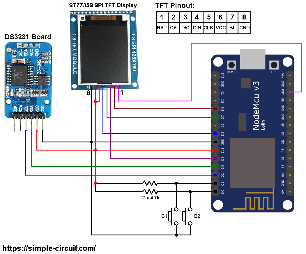
The ST7735 display is connected to the NodeMCU board as follows:
RST pin is connected to NodeMCU reset pin (RST),
CS pin is connected to D8 (ESP8266EX GPIO15),
D/C pin is connected to D4 (ESP8266EX GPIO2),
DIN (MOSI) pin is connected to D7 (ESP8266EX GPIO13),
CLK (SCK) pin is connected to D5 (ESP8266EX GPIO14),
VCC and BL are connected to pin 3V3,
GND is connected to pin GND of the NodeMCU board.
Pins D5 (GPIO14), D7 (GPIO13) and D8 (GPIO15) are hardware SPI module pins of the ESP8266EX microcontroller respectively for SCK (serial clock), MOSI (master-out slave-in) and CS (chip select).
The DS3231 RTC module SCL (serial clock) and SDA (serial data) pins are respectively connected to NodeMCU pins D3 (GPIO0) and D2 (GPIO4).
The two push buttons which are connected to NodeMCU pins D1 (GPIO5) and D0 (GPIO16) are for setting time & date of the clock.
NodeMCU with DS3231 RTC and ST7735 TFT code:
The following Arduino code requires 3 libraries from Adafruit Industries:
The first library is a driver for the ST7735 TFT display, download link is below:
Adafruit ST7735 TFT library —-> direct link
The 2nd library is Adafruit graphics library which can be downloaded from the following link
Adafruit graphics library —-> direct link
The third library is real time clock library (for DS3231), download link is below:
Adafruit RTC library —-> direct link
After the download, go to Arduino IDE —> Sketch —> Include Library —> Add .ZIP Library … and browse for the .zip file (previously downloaded).
The same thing for the other library files.
Hints:
The previous 3 libraries (& Wire library) are included in the main code as follows:
1 2 3 4 | #include <Wire.h> // include Wire library (required for I2C devices) #include <Adafruit_GFX.h> // include Adafruit graphics library #include <Adafruit_ST7735.h> // include Adafruit ST7735 TFT library #include <RTClib.h> // include Adafruit RTC library |
The connection of ST7735 TFT display with the NodeMCU is as shown below where the display is connected to hardware SPI module of the NodeMCU (pins: SCK and MOSI):
1 2 3 4 5 6 7 8 | // ST7735 TFT module connections #define TFT_RST -1 // TFT RST pin is connected to NodeMCU reset pin #define TFT_CS D8 // TFT CS pin is connected to NodeMCU pin D8 (GPIO15) #define TFT_DC D4 // TFT DC pin is connected to NodeMCU pin D4 (GPIO2) // initialize ST7735 TFT library with hardware SPI module // SCK (CLK) ---> NodeMCU pin D5 (GPIO14) // MOSI(DIN) ---> NodeMCU pin D7 (GPIO13) Adafruit_ST7735 tft = Adafruit_ST7735(TFT_CS, TFT_DC, TFT_RST); |
Functions used in the code:
bool debounce (): this function is for button B1 debounce, returns 1 if button is debounced.
void RTC_display(): prints day of the week, date and time on the display.
byte edit(byte parameter): this function is for setting the real time clock, returns the edited parameter.
Rest of code is described through comments.
Full Arduino code:
1 2 3 4 5 6 7 8 9 10 11 12 13 14 15 16 17 18 19 20 21 22 23 24 25 26 27 28 29 30 31 32 33 34 35 36 37 38 39 40 41 42 43 44 45 46 47 48 49 50 51 52 53 54 55 56 57 58 59 60 61 62 63 64 65 66 67 68 69 70 71 72 73 74 75 76 77 78 79 80 81 82 83 84 85 86 87 88 89 90 91 92 93 94 95 96 97 98 99 100 101 102 103 104 105 106 107 108 109 110 111 112 113 114 115 116 117 118 119 120 121 122 123 124 125 126 127 128 129 130 131 132 133 134 135 136 137 138 139 140 141 142 143 144 145 146 147 148 149 150 151 152 153 154 155 156 157 158 159 160 161 162 163 164 165 166 167 168 169 170 171 172 173 174 175 176 177 178 179 180 181 182 183 184 185 186 187 188 189 190 191 192 193 194 195 196 197 198 199 200 201 | /************************************************************************** * * ESP8266 NodeMCU real time clock with ST7735S TFT display and DS3231. * This is a free software with NO WARRANTY. * http://simple-circuit.com/ * *************************************************************************/ #include <Wire.h> // include Wire library (required for I2C devices) #include <Adafruit_GFX.h> // include Adafruit graphics library #include <Adafruit_ST7735.h> // include Adafruit ST7735 TFT library #include <RTClib.h> // include Adafruit RTC library // ST7735 TFT module connections #define TFT_RST -1 // TFT RST pin is connected to NodeMCU reset pin #define TFT_CS D8 // TFT CS pin is connected to NodeMCU pin D8 (GPIO15) #define TFT_DC D4 // TFT DC pin is connected to NodeMCU pin D4 (GPIO2) // initialize ST7735 TFT library with hardware SPI module // SCK (CLK) ---> NodeMCU pin D5 (GPIO14) // MOSI(DIN) ---> NodeMCU pin D7 (GPIO13) Adafruit_ST7735 tft = Adafruit_ST7735(TFT_CS, TFT_DC, TFT_RST); // initialize RTC library RTC_DS3231 rtc; DateTime now; const int button1 = D1; // button B1 is connected to NodeMCU D1 (GPIO5) const int button2 = D0; // button B2 is connected to NodeMCU D0 (GPIO16) void setup(void) { pinMode(button1, INPUT); pinMode(button2, INPUT); tft.initR(INITR_BLACKTAB); // initialize a ST7735S chip, black tab tft.fillScreen(ST7735_BLACK); // fill screen with black color tft.drawFastHLine(0, 20, tft.width(), ST7735_BLUE); // draw horizontal blue line at position (0, 20) tft.drawFastHLine(0, 75, tft.width(), ST7735_BLUE); // draw horizontal blue line at position (0, 75) tft.drawFastHLine(0, 130, tft.width(), ST7735_BLUE); // draw horizontal blue line at position (0, 130) tft.setTextColor(ST7735_WHITE, ST7735_BLACK); // set text color to white and black background tft.setTextSize(1); // text size = 1 tft.setCursor(4, 0); // move cursor to position (4, 0) pixel tft.print("NODEMCU + ST7735 TFT"); tft.setCursor(28, 10); // move cursor to position (28, 10) pixel tft.print("+ DS3231 RTC"); tft.setCursor(14, 134); // move cursor to position (14, 134) pixel tft.print("CHIP TEMPERATURE:"); tft.setTextSize(2); // text size = 2 tft.setTextColor(ST7735_MAGENTA, ST7735_BLACK); // set text color to magneta and black background tft.setCursor(37, 84); // move cursor to position (37, 84) pixel tft.print("TIME:"); // print °C tft.drawCircle(90, 148, 2, ST7735_RED); // print degree symbol ( ° ) tft.setCursor(95, 146); // move cursor to position (95, 146) pixel tft.setTextColor(ST7735_RED, ST7735_BLACK); // set text color to red and black background tft.print("C"); Wire.begin(D3, D2); // set I2C pins [SDA = D3, SCL = D2], default clock is 100kHz rtc.begin(); // initialize RTC chip } // a small function for button1 (B1) debounce bool debounce () { byte count = 0; for(byte i = 0; i < 5; i++) { if ( !digitalRead(button1) ) count++; delay(10); } if(count > 2) return 1; else return 0; } void RTC_display() { char dow_matrix[7][10] = {"SUNDAY", "MONDAY", "TUESDAY", "WEDNESDAY", "THURSDAY", "FRIDAY", "SATURDAY"}; byte x_pos[7] = {29, 29, 23, 11, 17, 29, 17}; static byte previous_dow = 8; // print day of the week if( previous_dow != now.dayOfTheWeek() ) { previous_dow = now.dayOfTheWeek(); tft.fillRect(11, 29, 108, 14, ST7735_BLACK); // draw rectangle (erase week day from the display) tft.setCursor(x_pos[previous_dow], 29); tft.setTextColor(ST7735_CYAN, ST7735_BLACK); // set text color to cyan and black background tft.print( dow_matrix[now.dayOfTheWeek()] ); } // print date tft.setCursor(4, 52); tft.setTextColor(ST7735_YELLOW, ST7735_BLACK); // set text color to yellow and black background tft.printf( "%02u-%02u-%04u", now.day(), now.month(), now.year() ); // print time tft.setCursor(16, 107); tft.setTextColor(ST7735_GREEN, ST7735_BLACK); // set text color to green and black background tft.printf( "%02u:%02u:%02u", now.hour(), now.minute(), now.second() ); } byte edit(byte parameter) { static byte i = 0, y_pos, x_pos[5] = {4, 40, 100, 16, 52}; if(i < 3) { tft.setTextColor(ST7735_YELLOW, ST7735_BLACK); // set text color to green and black background y_pos = 52; } else { tft.setTextColor(ST7735_GREEN, ST7735_BLACK); // set text color to yellow and black background y_pos = 107; } while( debounce() ); // call debounce function (wait for B1 to be released) while(true) { while( !digitalRead(button2) ) { // while B2 is pressed parameter++; if(i == 0 && parameter > 31) // if day > 31 ==> day = 1 parameter = 1; if(i == 1 && parameter > 12) // If month > 12 ==> month = 1 parameter = 1; if(i == 2 && parameter > 99) // If year > 99 ==> year = 0 parameter = 0; if(i == 3 && parameter > 23) // if hours > 23 ==> hours = 0 parameter = 0; if(i == 4 && parameter > 59) // if minutes > 59 ==> minutes = 0 parameter = 0; tft.setCursor(x_pos[i], y_pos); tft.printf("%02u", parameter); delay(200); // wait 200ms } tft.fillRect(x_pos[i], y_pos, 22, 14, ST7735_BLACK); unsigned long previous_m = millis(); while( (millis() - previous_m < 250) && digitalRead(button1) && digitalRead(button2)) ; tft.setCursor(x_pos[i], y_pos); tft.printf("%02u", parameter); previous_m = millis(); while( (millis() - previous_m < 250) && digitalRead(button1) && digitalRead(button2)) ; if(!digitalRead(button1)) { // if button B1 is pressed i = (i + 1) % 5; // increment 'i' for the next parameter return parameter; // return parameter value and exit } } } // main loop void loop() { if( !digitalRead(button1) ) // if B1 is pressed if( debounce() ) // call debounce function (make sure B1 is pressed) { //while( debounce() ); // call debounce function (wait for B1 to be released) byte day = edit( now.day() ); // edit date byte month = edit( now.month() ); // edit month byte year = edit( now.year() - 2000 ); // edit year byte hour = edit( now.hour() ); // edit hours byte minute = edit( now.minute() ); // edit minutes // write time & date data to the RTC chip rtc.adjust(DateTime(2000 + year, month, day, hour, minute, 0)); while( debounce() ); // call debounce function (wait for button B1 to be released) } now = rtc.now(); // read current time and date from the RTC chip RTC_display(); // diaplay time & calendar // read chip temperature Wire.beginTransmission(0x68); // start I2C protocol with DS3231 address Wire.write(0x11); // send register address (temperature MSB) Wire.endTransmission(false); // I2C restart Wire.requestFrom(0x68, 2); // request 2 bytes from DS3231 and release I2C bus at end of reading byte t_msb = Wire.read(); // read temperature MSB byte t_lsb = Wire.read(); // read temperature LSB // print chip temperature uint16_t chip_temp = (uint16_t)t_msb << 2 | t_lsb >> 6; tft.setCursor(11, 146); tft.setTextColor(ST7735_RED, ST7735_BLACK); // set text color to red and black background if(t_msb & 0x80) { chip_temp |= 0xFC00; tft.printf("-%02u.%02u", abs((int)chip_temp * 25) / 100, abs((int)chip_temp * 25) % 100); } else tft.printf(" %02u.%02u", (chip_temp * 25) / 100, (chip_temp * 25) % 100); delay(100); // wait 100ms } // end of code. |
The result of this project should be as the one shown below where Arduino UNO board is used:
Discover more from Simple Circuit
Subscribe to get the latest posts sent to your email.