In this WordPress blog there are several topics showing how to measure AC and DC voltages using Arduino boards and Microchip PIC® microcontrollers (MCUs).
This is another one that shows how to build an isolated AC voltage measurement circuit using Arduino UNO (or similar) board with true RMS calculations.
The RMS (effective) value of the voltage under measure is sent to the laptop which can be printed on Arduino IDE serial monitor tool and also displayed on a 1602 LCD screen.
Hints:
No warranty is provided with this project, so do it at your own risk!
A part of project circuit may be subjected to a high voltage level which is very harmful to human body, so please be-careful!
Abbreviations:
AC: Alternating Current.
DC: Direct Current.
TRMS (True RMS): True Root Mean Square.
ADC: Analog-to-Digital Converter
PCB: Printed Circuit Board
DIY: Do It Yourself
Op amp: operational amplifier
AC Voltage measurement with Arduino board and LCD circuit:
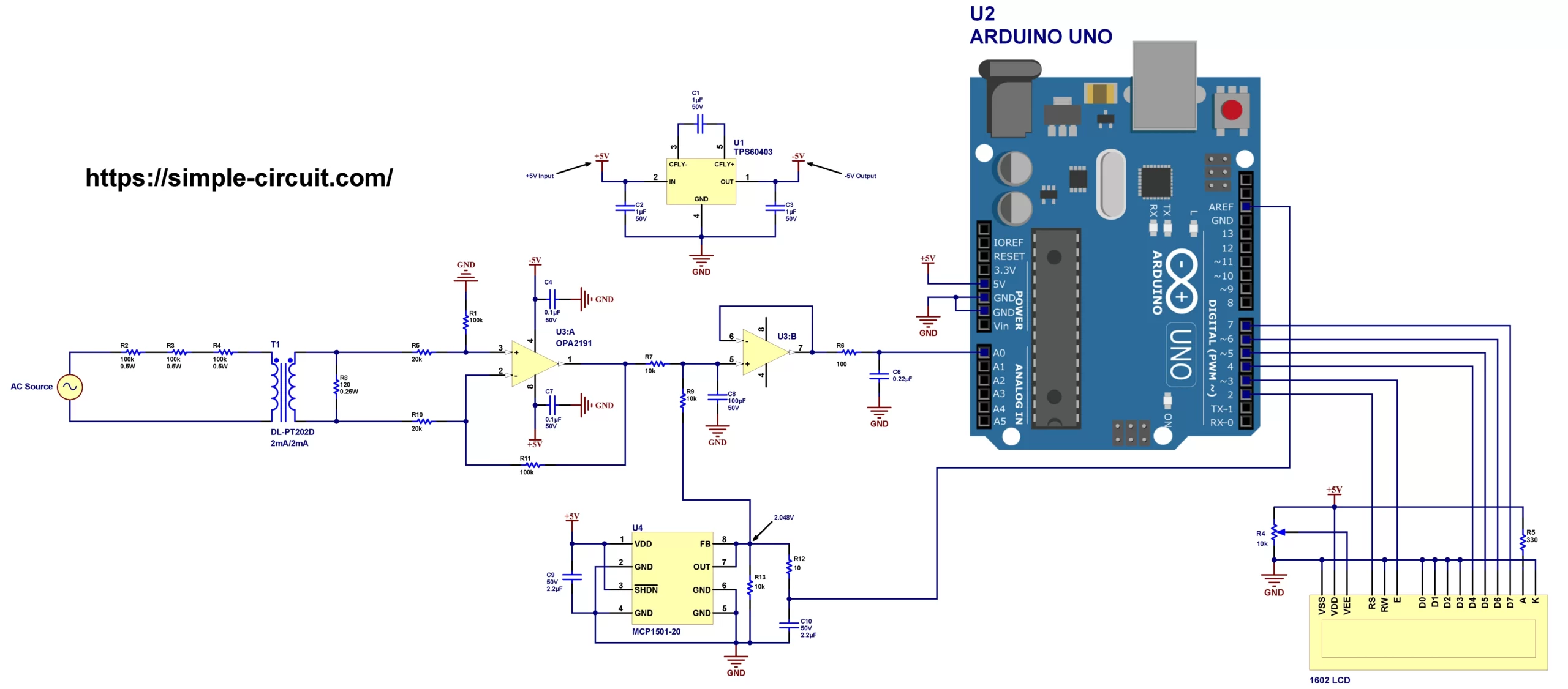
Project circuit diagram is shown below (click on the image to view the image in higher resolution).
Hardware required:
This is a summary of circuit required parts (circuit schematic diagram may contain some component parameters not mentioned below).
- Arduino UNO or equivalent board such as Arduino Nano, Mini (U2) —> ATmega328P datasheet
- DL-PT202D 2mA/2mA voltage sensor transformer (T1)
- OPA2191 op amp (U3) —> details
- MCP1501-20 2.048 voltage reference (U4) —> details
- TPS60403 charge pump voltage inverter (U1) —> details
- 1602 LCD screen
- 2 x 2.2uF capacitor (C9, C10)
- 3 x 1uF capacitor (C1, C2, C3)
- 0.22uF capacitor (C6)
- 2 x 0.1uF capacitor (C4, C7)
- 100pF capacitor (C8)
- 5 x 100k ohm resistor (R1, R2, R3, R4, R11)
- 2 x 20k ohm resistor (R5, R10)
- 3 x 10k ohm resistor (R7, R9, R13)
- 330 ohm resistor (R15)
- 120 ohm resistor (R8)
- 100 ohm resistor (R6)
- 10 ohm resistor (R12)
- 10k ohm variable resistor (R14)
- Breadboard & jumper wires
Circuit description:
The voltage to measure terminals is indicated in the circuit diagram as ‘AC Source’, we can apply an AC voltage up to 500V, this means we can measure home phase-to-natural (230V) and phase-to-phase (400V) voltages.
The two AC voltage source terminals are connected to DL-PT202D transformer (T1) through 3 current limiting resistors each of 100k ohm (R2, R3 & R4), the tolerance of these resistors should be 1% or lower in order to get better results, voltage rating of each resistor should be greater than or equal to 200V with rated power of 0.5W or higher. This transformer is just a current-type voltage transformer with ratio of 1000:1000, it converts an AC current on the primary to another equal one on the secondary. The maximum working current that may be applied to the primary is 2 mA RMS.
There are many alternatives to the voltage transformer that I’m using such as ZMPT112, and any other replacement should have the same voltage rating (or higher) and ratio (2mA/2mA).
This type of transformers gives a significant safety factor to the circuit as it provide a galvanic isolation between the high voltage mains circuit and the low voltage control circuit which is in a direct contact with human body and other equipments. They also have a small size, low cost and require few components.
Since the voltage transformer used in this project is a current type then its secondary shouldn’t be kept floating, a resistor (R8) with resistance of 120 Ohm is connected in parallel with the secondary of the voltage transformer and hence the current is converted to voltage.
The ratio of the voltage transformer circuit including the resistors R2, R3, R4 & R8 is:
120/300k = 1/2500.
That means a voltage of 400V RMS will be scaled down to 0.16 V = 160 mV RMS.
The voltage across the resistor R8 is amplified using OPA2191 differential amplifier from Texas Instruments, with a gain of 5.
The OPA2191 IC contains 2 independent op amps in one package which indicated in the circuit diagram by U3:A and U3:B. A bipolar supply of ±5 V is used to power the IC.
To get a negative voltage of -5 V I used TPS60403 60mA charge pump voltage inverter from Texas Instruments. The TPS60403 device automatically generates -5 V from the +5 V supply.
The 5V positive of the OPA2191 and the TPS60403 comes from the Arduino board.
The second op amp of the OPA2191 with resistors R7 & R9 are used to apply a gain of 0.5 and add an offset voltage of 1.024 V to the input signal. The OPA2191 also provides a low impedance source to the Arduino microcontroller ADC converter.
With the two op amp circuit gains (5 and 0.5) the overall gain of the circuit becomes:
5 x 0.5 x 1/2500 = 1/1000,
so with an applied sine wave AC voltage of 500 V the output will be 500 mV (707 mV peak).
The MCP1501-20 high-precision buffered voltage reference from Microchip is used to get a precise voltage of 2.048V which is then used as a positive voltage reference for the Arduino board microcontroller (ATmega328P) ADC module. Its filtered output is connected to AREF pin. This IC is also supplied from the Arduino board with 5V.
The 1602 LCD screen (2 rows and 16 columns) is used to display the RMS value of the applied voltage, it is connected to the Arduino board as follows:
RS —> Arduino digital pin 2
E —> Arduino digital pin 3
D4 —> Arduino digital pin 4
D5 —> Arduino digital pin 5
D6 —> Arduino digital pin 6
D7 —> Arduino digital pin 7
VSS, RW, D0, D1, D2, D3 and K are connected to GND,
VEE to the 10k Ohms variable resistor (or potentiometer) output,
VDD to Arduino 5V and A to Arduino 5V through 330 ohm resistor.
VEE pin is used to control the contrast of the LCD. A (anode) and K (cathode) are the back light LED pins.
AC Voltage measurement with Arduino board and LCD code:
Project code is the one below, it was tested with Arduino Nano board.
This Arduino code calculates average and RMS values of AC signals, the average value is just used in the RMS calculations. The MCU only shows the RMS value of the applied voltage on the LCD and serial monitor.
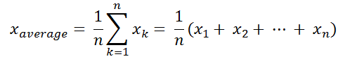
Simply the average (mean or DC offset) value in discrete-time is the sum of all sample values divided by number of samples:
and the RMS value in discrete-time can be calculated using the following equation:

The Arduino uno and similar boards microcontroller (ATmega328P) contains a 10-bit ADC module, with a positive voltage reference of 2.048 V, a 0 V is digitally represented by 0 and a 2.048 V is represented by 1023.
Programming hints:
As we have a 10-bit ADC module working in the range [0, 2.048V], the MCU makes 64 samples every 1 cycle and save the sampled data in an array named _array.
For a 50 Hz signal the period is 20 ms, the MCU takes one sample every 20000/64 = 312.5 us. I used Timer1 compare match interrupt every 312.5 us to initiate a new analog to digital conversion and once the conversion is complete ADC interrupt saves the digital value on the the array variable _array. The array element is incremented every new reading until the filling of all elements and the completion of the cycle.
The Arduino microcontroller runs @ 16MHz (16 MIPS), to get an interrupt every 312.5 us Timer1 is configured to work also @ 16MHz clock (prescaler = 1), this means Timer1 will make 5000 ticks in a duration of 312.5 us (16 x 312.5 = 5000).
For a 60 Hz waveform the period is 16.67 ms and Timer1 needs to make 4167 ticks.
Full Arduino code:
1 2 3 4 5 6 7 8 9 10 11 12 13 14 15 16 17 18 19 20 21 22 23 24 25 26 27 28 29 30 31 32 33 34 35 36 37 38 39 40 41 42 43 44 45 46 47 48 49 50 51 52 53 54 55 56 57 58 59 60 61 62 63 64 65 66 67 68 69 70 71 72 73 74 75 76 77 78 79 80 81 82 83 84 85 86 87 88 89 90 91 92 93 94 95 96 97 98 99 | /************************************************************************ * * AC voltage measurement using Arduino and isolation voltage transformer. * Calculated voltage values are printed on 1602 LCD screen and serial monitor. * This is a free software with NO WARRANTY - Use it at your own risk! * http://simple-circuit.com/ * ************************************************************************/ #include <LiquidCrystal.h> // include Arduino LCD library // LCD module connections (RS, E, D4, D5, D6, D7) LiquidCrystal lcd(2, 3, 4, 5, 6, 7); void setup() { delay(100); Serial.begin(9600); lcd.begin(16, 2); // set up the LCD's number of columns and rows lcd.setCursor(0, 0); // move cursor to column 0, row 0 [position (0, 0)] lcd.print("AC Voltage ="); cli(); // disable global interrupts // disable Timer0 overflow interrupt (delay() & millis() functions will not work!) TIMSK0 &= ~(1 << TOIE0); // Timer1 configuration TCCR1A = 0; // normal operation of Timer1, OC1A/OC1B disconnected. // output compare register OCR1A = 5000, timer will reset when reaches this value // for 60 Hz voltage use: OCR1A = 0x1047; OCR1A = 0x1388; // (1 << WGM12): clear Timer on compare match (CTC) // (1 << CS10): set Timer clock source to CLKio (no prescaling) TCCR1B = 0 | (1 << WGM12) | (1 << CS10); TIMSK1 = 0 | (1 << OCIE1A); // enable output compare A match interrupt // ADC configuration ADMUX = 0; // select channel 0, ADC right adjust result & voltage reference is AREF pin ADCSRA = 0 | (1 << ADEN) | (1 << ADPS2) | (1 << ADPS1) | (1 << ADPS0); sei(); // enable global interrupts } const uint8_t n = 64; // number of samples volatile int16_t _array[n]; // samples array volatile uint8_t m; volatile uint16_t _offset = 0; uint32_t ch_voltage; // Timer1 compare match A ISR ISR(TIMER1_COMPA_vect) { ADCSRA |= (1 << ADSC); // start ADC conversion } // ADC conversion complete ISR ISR(ADC_vect) { _array[m] = ADCW; _offset += _array[m]; m++; } void loop() { m = 0; _offset = 0; ch_voltage = 0; TCNT1 = 0; // reset Timer1 ADCSRA |= (1 << ADIE); // enable ADC conversion complete interrupt TIMSK1 |= (1 << OCIE1A); // enable output compare A match interrupt while (m < n) ; // wait for 1 cycle to complete (duration of 20 ms @ 50 Hz) TIMSK1 &= ~(1 << OCIE1A); // disable output compare A match interrupt ADCSRA &= ~(1 << ADIE); // disable ADC conversion complete interrupt _offset = _offset / n; // caculate signal average value (dc offset) // calculate voltage RMS value for ( uint8_t i = 0; i < n; i++ ) { int16_t j = _array[i] - _offset ; ch_voltage += ( (int32_t)j * j); } ch_voltage = ch_voltage / n; // Now calculate real voltage RMS value applied to MCU analog channel // 2.0 = 2048/1024 where 2048 is ADC +ive VREF = 2048 mV and 1024 is 10-bit ADC max digital value // Note that this voltage is the same as the AC voltage under measure (in Volts) as the hardware circuit ratio is 1000:1 ch_voltage = (sqrt(ch_voltage) * 2.0); Serial.print("Voltage = "); Serial.print(ch_voltage); Serial.println(" V"); // lcd.setCursor(0, 1); // move LCD cursor to column 0, row 1 [position (0, 1)] lcd.print(ch_voltage); lcd.print( " V "); TIMSK0 |= (1 << TOIE0); // enable Timer0 overflow interrupt delay(500); TIMSK0 &= ~(1 << TOIE0); // disable Timer0 overflow interrupt } // end of code. |
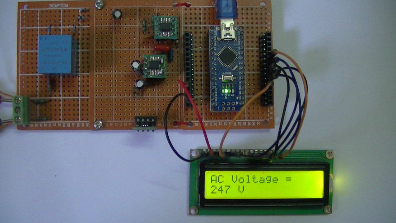
The following small video shows my DIY circuit for this project where an Arduino Nano is used:
Related Projects:
AC & DC Current Measurement with Arduino and LTSR 25-NP Sensor
AC Current Measurement using Arduino and Current Transformer
Measure AC & DC Currents with Arduino and ACS758 Sensor
Interfacing Arduino with Current Transformer – AC Current Measurement
AC Current Measurement using Arduino and Current Transformer
AC Voltage Measurement using PIC18F46K22 Microcontroller
Isolated AC Voltage Measurement with Arduino and AMC1301 Amplifier
Discover more from Simple Circuit
Subscribe to get the latest posts sent to your email.


“AC Voltage Measurement with Arduino Board and LCD”
How can this scheme be done with lm324?
If we examine it technically, what kind of shortcomings would there be?