After controlling 2 DC motors speed and direction of rotation with 2 potentiometers, now let’s make the same project but with IR remote control. First project is at the link below:
Two motors control using PIC16F887 and L293D
The microcontroller used in this project is PIC16F887 and the remote control is Car MP3 IR remote control which uses NEC protocol. Decoding of this remote control with PIC16F887 is done in the following project:
NEC Protocol decoder with PIC16F887 microcontroller
In this project 6 buttons are used for controlling the speed and rotation direction of the 2 motors, these buttons are shown in the following image:
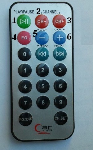
The code of each button are as shown in the following table (these codes will be used later in the C code):
Button Number | Function | Code |
1 | Motor 1 Start/Toggle direction | 0x40BF00FF |
2 | Motor 1 speed down | 0x40BF807F |
3 | Motor 1 speed up | 0x40BF40BF |
4 | Motor 2 Start/Toggle direction | 0x40BF20DF |
5 | Motor 2 speed down | 0x40BFA05F |
6 | Motor 2 speed up | 0x40BF609F |
Hardware Required:
- PIC16F887 microcontroller
- 2 x DC motor (I used 12V motors)
- L293D motor driver
- NEC IR remote control (I’m using Car MP3 as the one above)
- IR receiver
- 10K ohm resistor
- 47µF capacitor
- 5V and 12V voltage sources
- Breadboard
- Jumper wires
Two DC motors control with NEC IR remote control and PIC16F887 circuit:
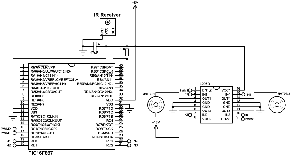
As shown in the circuit diagram the IR receiver output is connected to RB0 pin which is external interrupt pin of the PIC16F887 microcontroller.
The L293D IC is used to drive both motors in the two directions, the speed of the two motors is controlled the two PWM signals which come from the microcontroller. PWM1 controls motor 1 speed and PWM2 controls motor 2 speed. Motor 1 direction is controlled with IN1 and IN2 pins of the L293D, these pins are connected to RD0 and RD1 of the PIC16F887. Motor 2 is controlled with pin IN3 and IN4 of the L293D, IN3 is connected to RD2 and IN4 is connected to RD3 of the microcontroller. When IN1 = IN2 = 0, motor 1 stops, when IN1 = 1 and IN2 = 0 motor 1 moves in the first direction, when IN1 = 0 and IN2 = 1 motor 1 moves in the second direction. The same thing for motor 2 with pins IN3 and IN4.
The 10K ohm resistor is used to minimize the IR receiver output noise.
In the circuit there are two voltage sources, one with 5V which supplies most of the circuit and the other one with 12V which supplies only the L293D IC. The 12V source depends on the motors nominal voltage.
In this project the PIC16F887 uses its internal oscillator and MCLR pin function is disabled.
Two DC motors control with NEC IR remote control CCS C code:
Project C code is as shown below. It has been tested with CCS PIC C compiler version 5.051.
PIC16F887 hardware external interrupt and Timer1 are used to decode the IR remote control. Timer1 is used to measure pulses and spaces widths and its interrupt (Timer1 interrupt) is used to reset the decoding process in case of very long pulse or space (time out). Timer1 is configured to increment every 1µs using the following command line:
setup_timer_1( T1_INTERNAL | T1_DIV_BY_2 );
But Timer1 module will not start until the microcontroller receives an interrupt on pin RB0 (interrupt edge from high to low).
The motor speed changes whenever the duty cycle of the PWM signal changes, and thus if the microcontroller receives speed up button code it will increment the duty cycle, then motor speed will be increased, and if the microcontroller receives speed down button code, the duty cycle will be decreased which causes the motor to decrease its speed.
At start up , both motors are stopped because all PORTD pins are zeroes with the command output_d(0); and when start/toggle direction button is pressed, the motor will start (if there is sufficient duty cycle otherwise the duty cycle have to be increased), and the same button pressed again the motor will change its direction of rotation.
The full C code is shown below.
1 2 3 4 5 6 7 8 9 10 11 12 13 14 15 16 17 18 19 20 21 22 23 24 25 26 27 28 29 30 31 32 33 34 35 36 37 38 39 40 41 42 43 44 45 46 47 48 49 50 51 52 53 54 55 56 57 58 59 60 61 62 63 64 65 66 67 68 69 70 71 72 73 74 75 76 77 78 79 80 81 82 83 84 85 86 87 88 89 90 91 92 93 94 95 96 97 98 99 100 101 102 103 104 105 106 107 108 109 110 111 112 113 114 115 116 117 118 119 120 121 122 123 124 125 126 127 128 129 130 131 132 133 134 135 136 137 138 139 140 141 142 143 144 145 146 147 148 149 150 151 152 153 | // 2 Motors control with NEC IR remote control CCS C code // Used MCU: PIC16F887 // Internal oscillator used @ 8MHz // Used remote control: Car MP3 IR remote control // PWM1 and PWM2 modules are used to control motor 1 and motor 2 speeds respectively #include <16F887.h> #fuses NOMCLR NOBROWNOUT NOLVP INTRC_IO #use delay(clock = 8MHz) short nec_ok = 0, repeated = 0, m1_dir = 0, m2_dir = 0; unsigned int8 nec_state = 0, i, duty1 = 0, duty2 = 0; unsigned int32 nec_code; #INT_EXT // External interrupt void ext_isr(void){ unsigned int16 time; if(nec_state != 0){ time = get_timer1(); // Store Timer1 value set_timer1(0); // Reset Timer1 } switch(nec_state){ case 0 : // Start receiving IR data (we're at the beginning of 9ms pulse) setup_timer_1( T1_INTERNAL | T1_DIV_BY_2 ); // Enable Timer1 module with internal clock source and prescaler = 2 set_timer1(0); // Reset Timer1 value nec_state = 1; // Next state: end of 9ms pulse (start of 4.5ms space) i = 0; ext_int_edge( L_TO_H ); // Toggle external interrupt edge break; case 1 : // End of 9ms pulse if((time > 9500) || (time < 8500)){ // Invalid interval ==> stop decoding and reset nec_state = 0; // Reset decoding process setup_timer_1(T1_DISABLED); // Stop Timer1 module } else nec_state = 2; // Next state: end of 4.5ms space (start of 562µs pulse) ext_int_edge( H_TO_L ); // Toggle external interrupt edge break; case 2 : // End of 4.5ms space if((time > 5000) || (time < 1500)){ // Invalid interval ==> stop decoding and reset nec_state = 0; // Reset decoding process setup_timer_1(T1_DISABLED); // Stop Timer1 module break; } nec_state = 3; // Next state: end of 562µs pulse (start of 562µs or 1687µs space) if(time < 3000) // Check if previous code is repeated repeated = 1; ext_int_edge( L_TO_H ); // Toggle external interrupt edge break; case 3 : // End of 562µs pulse if((time > 700) || (time < 400)){ // Invalid interval ==> stop decoding and reset nec_state = 0; // Reset decoding process setup_timer_1(T1_DISABLED); // Disable Timer1 module } else{ // Check if the repeated code is for buttons 2, 3, 5 or 6 if(repeated && (nec_code == 0x40BF807F || nec_code == 0x40BF40BF || nec_code == 0x40BFA05F || nec_code == 0x40BF609F)){ repeated = 0; nec_ok = 1; // Decoding process is finished with success disable_interrupts(INT_EXT); // Disable the external interrupt break; } nec_state = 4; // Next state: end of 562µs or 1687µs space ext_int_edge( H_TO_L ); // Toggle external interrupt edge break; } case 4 : // End of 562µs or 1687µs space if((time > 1800) || (time < 400)){ // Invalid interval ==> stop decoding and reset nec_state = 0; // Reset decoding process setup_timer_1(T1_DISABLED); // Disable Timer1 module break; } if( time > 1000) // If space width > 1ms (short space) bit_set(nec_code, (31 - i)); // Write 1 to bit (31 - i) else // If space width < 1ms (long space) bit_clear(nec_code, (31 - i)); // Write 0 to bit (31 - i) i++; if(i > 31){ // If all bits are received nec_ok = 1; // Decoding process is finished with success disable_interrupts(INT_EXT); // Disable the external interrupt } nec_state = 3; // Next state: end of 562µs pulse (start of 562µs or 1687µs space) ext_int_edge( L_TO_H ); // Toggle external interrupt edge } } #INT_TIMER1 // Timer1 interrupt (used for time out) void timer1_isr(void){ nec_state = 0; // Reset decoding process ext_int_edge( H_TO_L ); // External interrupt edge from high to low setup_timer_1(T1_DISABLED); // Disable Timer1 module clear_interrupt(INT_TIMER1); // Clear Timer1 interrupt flag bit } void main(){ setup_oscillator(OSC_8MHZ); // Set internal oscillator to 8MHz output_d(0); enable_interrupts(GLOBAL); // Enable global interrupts enable_interrupts(INT_EXT_H2L); // Enable external interrupt clear_interrupt(INT_TIMER1); // Clear Timer1 interrupt flag bit enable_interrupts(INT_TIMER1); // Enable Timer1 interrupt setup_timer_2(T2_DIV_BY_16, 255, 1); // Set PWM frequency to 488Hz setup_ccp1(CCP_PWM); // Configure CCP1 module as PWM setup_ccp2(CCP_PWM); // Configure CCP2 module as PWM set_pwm1_duty(0); // Set PWM1 duty sycle set_pwm2_duty(0); // Set PWM2 duty sycle while(TRUE){ if(nec_ok){ // If the MCU receives a message from the remote control nec_ok = 0; // Reset decoding process nec_state = 0; setup_timer_1(T1_DISABLED); // Disable Timer1 module // Motor 1 if(nec_code == 0x40BF00FF && m1_dir){ // If button 1 is pressed (toggle rotation direction of motor 1) m1_dir = 0; nec_code = 0; output_high(PIN_D0); output_low(PIN_D1); } if(nec_code == 0x40BF00FF && !m1_dir){ // If button 1 is pressed (toggle rotation direction of motor 1) m1_dir = 1; output_low(PIN_D0); output_high(PIN_D1); } if(nec_code == 0x40BF40BF && duty1 < 255){ // If button 3 is pressed (increase motor 1 speed) duty1++; set_pwm1_duty(duty1); } if(nec_code == 0x40BF807F && duty1 > 0){ // If button 2 is pressed (decrease motor 1 speed) duty1--; set_pwm1_duty(duty1); } // Motor 2 if(nec_code == 0x40BF20DF && m2_dir){ // If button 4 is pressed (toggle rotation direction of motor 2) m2_dir = 0; nec_code = 0; output_high(PIN_D2); output_low(PIN_D3); } if(nec_code == 0x40BF20DF && !m2_dir){ // If button 4 is pressed (toggle rotation direction of motor 2) m2_dir = 1; output_low(PIN_D2); output_high(PIN_D3); } if(nec_code == 0x40BF609F && duty2 < 255){ // If button 6 is pressed (increase motor é speed) duty2++; set_pwm2_duty(duty2); } if(nec_code == 0x40BFA05F && duty2 > 0){ // If button 5 is pressed (decrease motor 2 speed) duty2--; set_pwm2_duty(duty2); } enable_interrupts(INT_EXT_H2L); // Enable external interrupt } } } |
The following video shows a hardware circuit of our project:


