A simple diode bridge rectifiers provide a fixed output voltage only and to obtain a controlled output voltage we need to replace the diodes by a phase-control thyristors, such as a Silicon Controlled Rectifier (SCR) semiconductor devices.
The output voltage of a controlled bridge rectifier is varied by controlling the turn-on delay, or firing angle, of the thyristors.
Thyristors are a family of power semiconductor devices. Basically, a Thyristor is a four-layer semiconductor device with PNPN structure and three junctions. It has three terminals: anode, cathode, and gate. The major types of the thyristor family are:
- Silicon Controlled Rectifier (SCR)
- TRIACs
- Gate turn-off thyristors (GTO)
Silicon Controlled Rectifier (SCR) is the most device known by the word ‘Thyristor’, it is widely used in phase controlled rectifiers such as single phase bridge rectifiers.
A Thyristor is turned-on by applying a short pulse between its gate and cathode terminals and turned-off due to line commutation.
Phase controlled rectifiers are simple and less expansive with high efficiency (above 95%). These converters enables the conversion of AC voltage to DC voltage and they are used extensively in industrial applications.
Types of Controlled Rectifiers:
Controlled rectifiers can be classified into two types depending on the input supply.
- Single-Phase controlled rectifier
- Three-Phase controlled rectifier
Each type can subdivided into:
- Semi-Controlled converter
- Fully-Controlled converter
A semi-controlled rectifier is a converter where half of the semiconductor switches are controlled, the other half is just a simple diodes, whereas in a fully-controlled rectifier all semiconductor devices are controlled.
For example, a single phase semi-controlled rectifier has two thyristors and two diodes, and a single phase fully-controlled rectifier consists of 4 thyristors.
Applications of Controlled Rectifiers:
This is a list of some applications of controlled rectifiers.
- AC-DC Converters: Controlled rectifiers can be used to convert AC to DC with variable output voltage.
- Battery Charging: Thyristor based rectifiers are widely used in industrial battery bank charging systems where a variable output voltage & current are required.
- Uninterruptable Power Supply (UPS) Systems: UPS systems are used to feed critical loads, a controlled rectifier is used to generate DC voltage for system batteries and inverter.
- Heating Control: Used to control output power delivered to electrical heaters.
- DC Motor Speed Control: By controlling the average DC voltage supplied to a motor, the speed can be simply adjusted.
The image below shows a single-phase semi controlled rectifier circuit:
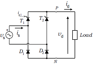
Working Principle:
The controlled rectifier operates similarly to the uncontrolled one, except that the thyristors used in the circuit can be turned on at a desired point in the AC cycle by applying a short pulse to the gate terminal. By controlling the firing angle, the average output voltage can be varied.
In the above circuit schematic, only two thyristors (SCR) T1 & T2 are required to control the output voltage Vd. Each thyristor is turned on by applying a sufficient voltage between its gate and cathode terminals and therefore a small current Ig flows through its gate terminal. Diodes D1 and D2 are simple rectifier diodes.
Full Wave Controlled Rectifier with Arduino Board Circuit:
This post shows how to implement a semi-controlled full wave rectifier based on Arduino uno board. Circuit schematic is shown below.
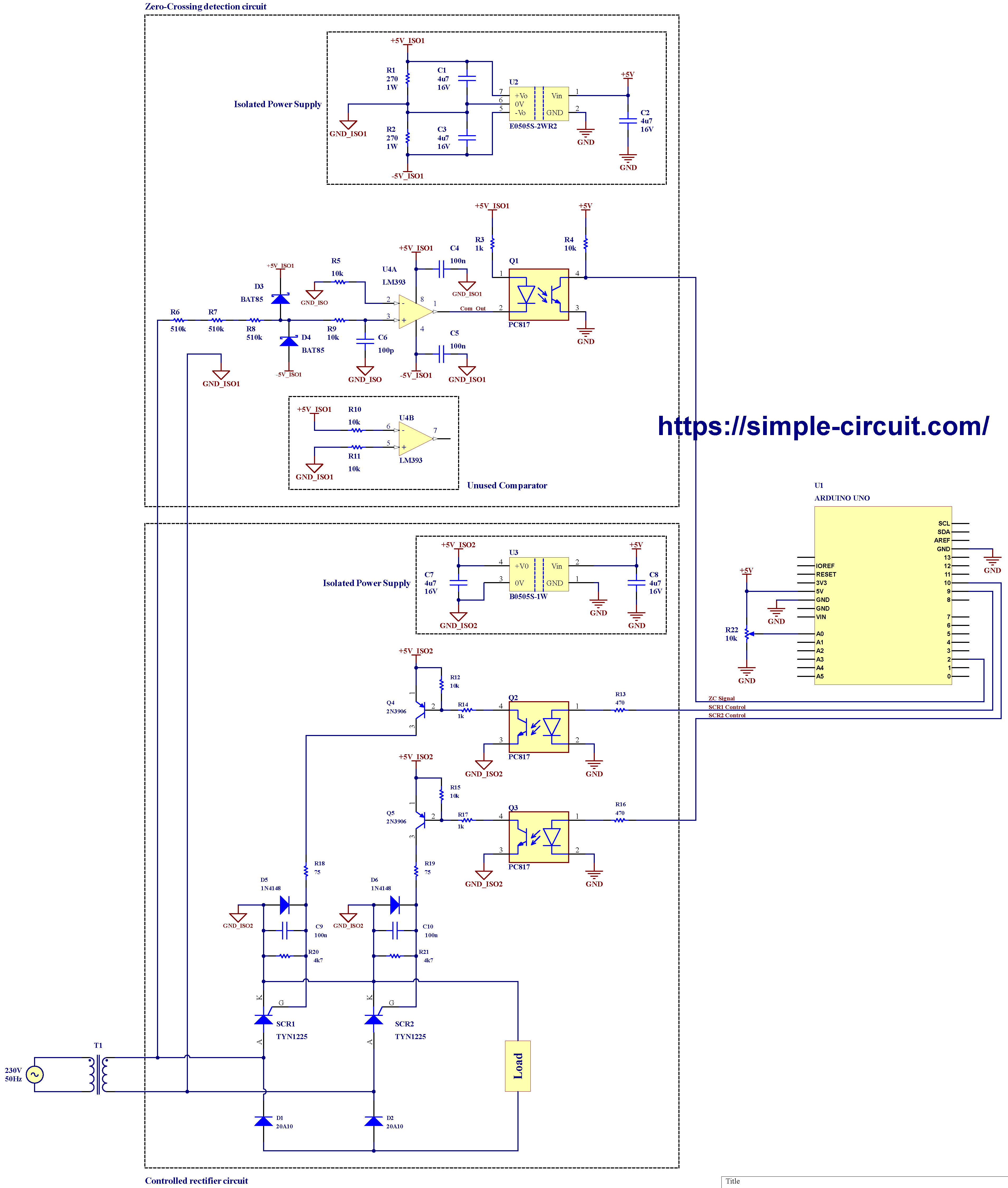
The firing angle is controlled with potentiometer R22 connected to Arduino analog channel 0. Changing the firing angle will change the output voltage, a low firing angle will lead to a high output voltage.
A Step down transformer T1 reduces the 230V input to a lower voltage. T1 Transformer should be selected according to application load. In my circuit, I’m using a transformer with rated primary voltage of 230V and secondary of 18V, the load is 12V lead acid battery, charging voltage is about 14.5V according to battery manufacturer.
Increasing output voltage normally will lead to an increase in output current, this may cause the transformer or rectifier components (SCRs and diodes) to be overloaded and therefor damaged after some time.
Rectifier Bridge components are: Silicon Controlled Rectifier SCR1 & SCR2, and Diodes D1 & D2. The load may be: incandescent light bulb (not LED lamp), battery, heater, electric motor…
The silicon controlled rectifier (SCR) devices used in this project are: TYN1225 from STMicroelectronics.
Note that the following signals are totally isolated from each other and there is no direct contact between them:
() GND, GND_ISO1, GND_ISO2.
() +5V, +5V_ISO1, -5V_ISO1, +5V_ISO2.
Hardware Required:
This is a list for the components used in this Arduino project.
- Arduino uno, or similar, board (U1) —> Board details —> ATmega328P datasheet
- E0505S-2WR Isolated Dual output DC/DC converter (U2) —> datasheet
- B0505S-1W Isolated DC/DC converter (U3) —> datasheet
- LM393 Dual differential comparator (U4) —> datasheet
- 2 x TYN1225 Silicon Controlled Rectifier (SCR) Thyristor (SCR1, SCR2) —> datasheet
- 2 x 20A10 Standard rectifier diode (D1, D2)
- 3 x PC817 Optocoupler (Q1, Q2, Q3)
- 2 x 2N3906 PNP Transistor (Q4, Q5)
- 2 x BAT85 Schottky diode (D3, D4)
- 2 x 1N4148 diode (D5, D6)
- 5 x 16V, 4.7uF electrolytic capacitor (C1, C2, C3, C7, C8)
- 4 x 100nF Ceramic capacitor (C4, C5, C9, C10)
- 100pF ceramic capacitor (C6)
- 3 x 510k Ohm resistor (R6, R7, R8)
- 7 x 10k Ohm resistor (R4, R5, R9, R10, R11, R12, R15)
- 2 x 4.7k Ohm resistor (R20, R21)
- 3 x 1k Ohm resistor (R3, R14, R17)
- 2 x 470 Ohm resistor (R13, R16)
- 2 x 270 Ohm resistor (R1, R2)
- 2 x 75 Ohm resistor (R18, R19)
- 10k Ohm potentiometer (R22)
- Step down transformer (T1)
Circuit Description:
Project circuit can be divided into two main parts:
a). Zero-crossing detection circuit, and
b). Controlled rectifier circuit.
a). Zero-Crossing Detection Circuit:
This circuit is used to determine the points at which the AC waveform crosses zero and sends the events to the Arduino board. The detection of zero-crossing events is required before executing the firing delay, or firing angle. The thyristor is fired by sending a pulse burst to its gate after the firing delay period has expired.
The zero-crossing detection circuit has an output isolated from the input. This increases the safety of low voltage control circuit including the Arduino board.
An optocoupler (Q1) is used to isolate zero crossing pulses signal generated from high voltage power circuit. An isolated DC-to-DC converter (U2) with input of 5V and dual output of ±5V is used to provide an isolated power source to the high voltage side. In this example I used the part E0505S-2WR3 from MORNSUN, there are many equivalents to this part that can be replaced with.
The input of U2 isolated DC/DC converter is 5V where pin Vin (#1) is connected to circuit positive supply +5V, and pin GND (#2) is connected to circuit ground. The +5V source comes from the Arduino board.
The output of the isolated DC/DC converter U2 is +5V_ISO1, GND_ISO1, and -5V_ISO1 where pin +Vo (#7) is the positive output and pin -Vo (#5) is the negative output, both outputs are with respect to pin 0V (#6).
More details about zero-crossing detection circuit in this post:
Isolated Zero Crossing Detection Circuit
b). Controlled rectifier circuit:
This circuit contains the semi-controlled bridge rectifier and the components required to provide the necessary firing voltage to thyristors SCR1 & SCR2.
The controlled rectifier circuit is also isolated from the low voltage circuit.
Another isolated power supply module is used to provide a 5V isolated source (U3). The input of U3 is 5V and the isolated output terminals are: +5V_ISO2 and GND_ISO2. U3 Isolated DC/DC converter is also powered from the Arduino board with voltage of 5V.
Two optocouplers, Q2 & Q3, are used to send isolated pulses to thyristors SCR1 & SCR2 respectively. The Arduino generates the required firing pulses according the to the AC waveform and the required output voltage.
The output voltage can be controlled with a potentiometer (R22) connected to Arduino analog channel 0.
Transistors Q4 & Q5 (PNP type) feeds thyristor gates with the required firing current. Resistors R18 & R19 limits gate currents to about 50 mA.
Other gate circuitry, D5 & D6, C9 & C10, R20 & R21, helps protecting thyristor gates, reduce noise, increase the dv/dt capability, and reduce turn-off time.
Full Wave Controlled Rectifier with Arduino Code:
The Arduino code was tested with Arduino board containing the Microchip ATmega328P 8-bit microcontroller running @ 16MHz. Arduino UNO Rev 3, NANO Rev 3, and similar boards, contain the same chip.
The firing angle is controlled with a potentiometer connected to Arduino analog channel 0. A changing in analog channel 0 voltage will cause the firing delay time to change.
In this example, the time between zero-crossing event and SCR firing point is measured by Timer2 module. Once the delay time elapsed the Arduino starts sending PWM signal to trigger the corresponding SCR.
Timer1 module is configured to generate two PWM signals on Arduino pins 9 and 10 with frequency of 3.9 kHz, one of them can be active at a time.
Rest of code is described through comments.
Full Arduino Code:
1 2 3 4 5 6 7 8 9 10 11 12 13 14 15 16 17 18 19 20 21 22 23 24 25 26 27 28 29 30 31 32 33 34 35 36 37 38 39 40 41 42 43 44 45 46 47 48 49 50 51 52 53 54 55 56 57 58 59 60 61 62 63 64 65 66 67 68 69 70 71 72 73 74 75 76 77 78 79 80 81 82 83 84 85 86 87 88 89 90 91 92 93 94 95 96 97 98 99 100 101 102 103 104 105 106 107 108 109 110 111 112 113 | /**************************************************************************************** * * Full wave controlled rectifier with Arduino. * A Semi-controlled rectifier is used with PWM gate pulses generated at pins 9 & 10. * This is a free software with NO WARRANTY - Use it at your own risk! * https://simple-circuit.com/ * ***************************************************************************************/ #define ZeroCrossing_Pin 2 enum State {ZC_Detect, Alpha_Delay}; uint8_t State; // Circuit state, may be one of the above enum bool ZC_Status; // Variable to store ZC status, may be 1 or 0 uint8_t FiringAngle; void setup(void) { delay(100); pinMode(ZeroCrossing_Pin, INPUT); pinMode(9, OUTPUT); // configure pin 9 as output pinMode(10, OUTPUT); // configure pin 10 as output digitalWrite(9, LOW); digitalWrite(10, LOW); // PWM configuration, pins 9 and 10 OCR1A = 50; // set PWM1 duty cycle (50µs pulse width, pin 9) OCR1B = 50; // set PWM2 duty cycle (50µs pulse width, pin 10) TCCR1B = 0x02; // set Timer1 clock to CLKio/8 (get PWM frequency of 3.9 kHz) TCCR1A = 0; TCCR2A = 0; // Timer2 Normal operation // ADC configuration ADMUX = 0x60; // set ADC +ive reference to AVCC // use left adjusted ADC result presentation // select analog channel 0 ADCSRA = 0x87; // enable ADC module // set ADC prescaler to 128 --> ADC CLK = 125kHz ZC_Status = debounce(); State = ZC_Detect; } // Digital input debounce function, returns 1 if 'HIGH' and 0 if 'LOW' bool debounce() { byte count = 0; for(byte i = 0; i < 10; i++) { if( digitalRead(ZeroCrossing_Pin) ) count++; delayMicroseconds(3); } if(count > 4) return 1; return 0; } // main loop void loop() { if( (ZC_Status != digitalRead(ZeroCrossing_Pin)) && (State == ZC_Detect) ) { bool ZC_Input = debounce(); if( ZC_Status != ZC_Input ) { TCCR1A = 0; // turn off PWM (pin 9 & 10) digitalWrite(9, LOW); digitalWrite(10, LOW); TCNT2 = 0; // Clear Timer2 register TIFR2 |= (1 << TOV2); // Clear Timer2 overflow flag TCCR2B = 0x07; // Timer2 clock source MCUclk/1024 = 16/1024 = 15.625 kHz FiringAngle = 255 - ADCH; // Read data from ADC register FiringAngle = map(FiringAngle, 0, 255, 0, 155); if(FiringAngle < 5) FiringAngle = 0; ADCSRA |= (1 << ADSC); // Start a new ADC conversion State = Alpha_Delay; ZC_Status = ZC_Input; } } // Firing angle delay if( (TCNT2 > FiringAngle) && (State == Alpha_Delay) ) { if(ZC_Status == 1) // Firing of SCR1, pin 9 (OC1A) TCCR1A = 0x81; else // Firing of SCR2, pin 10 (OC1B) TCCR1A = 0x21; State = ZC_Detect; } // Timer 2 overflow if( TIFR2 & 0x01) { TCCR1A = 0; // turn off PWM (pin 9 & 10) digitalWrite(9, LOW); digitalWrite(10, LOW); TIFR2 |= (1 << TOV2); // Clear Timer2 overflow flag TCCR2B = 0; // Stop Timer2 State = ZC_Detect; } } // end of code. |
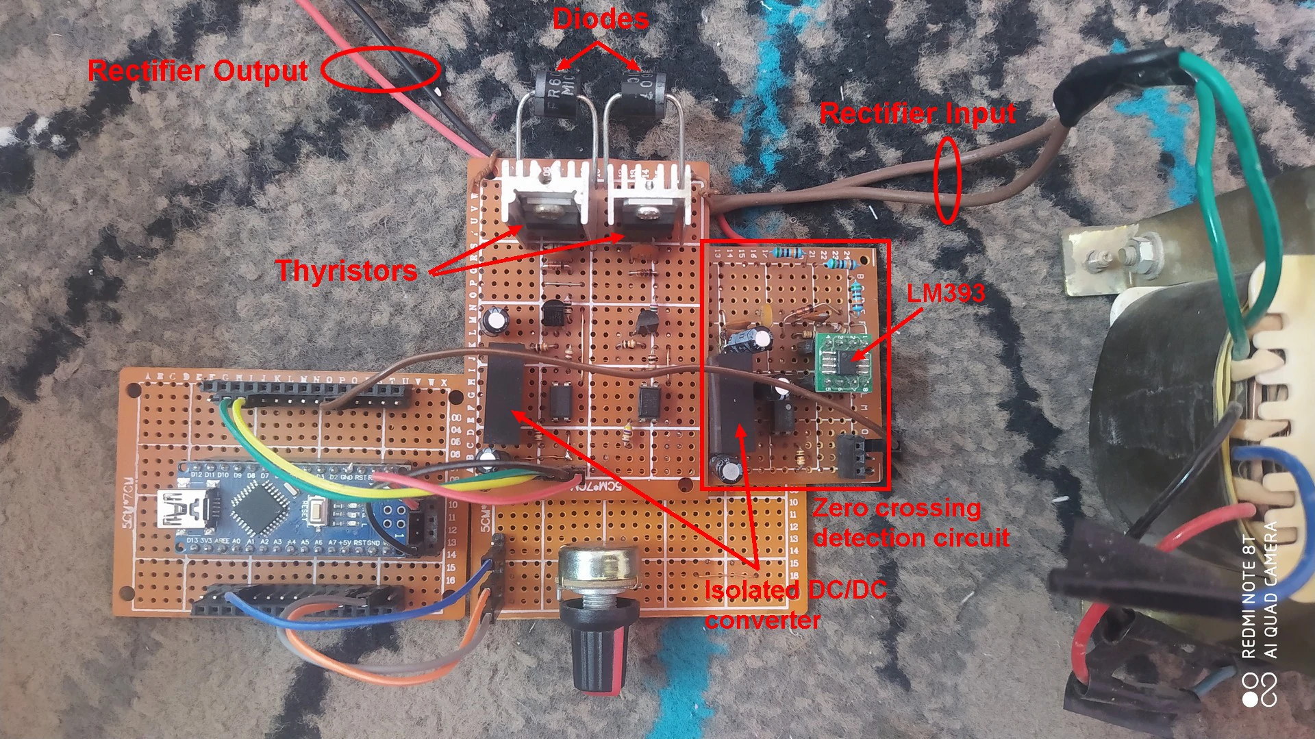
The picture below shows my DIY hardware circuit of the controlled rectifier. I used a 12V lead acid battery as a load for testing purpose:
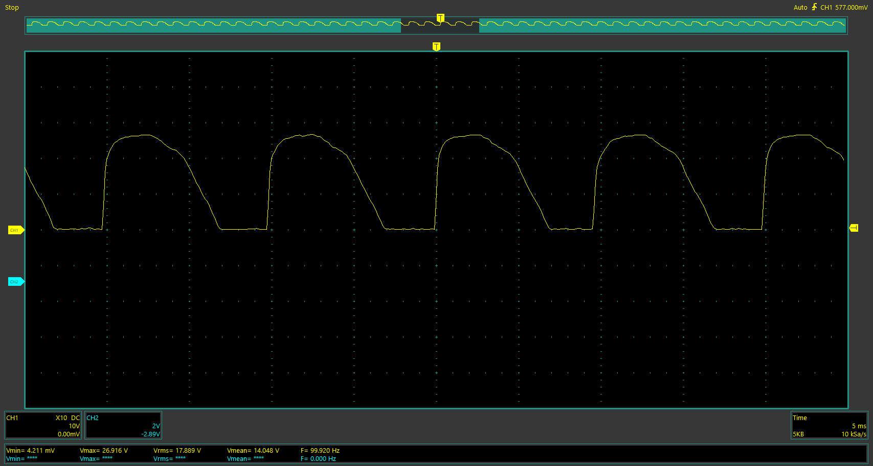
This second image shows a waveform of the controlled rectifier output voltage with pure resistive load where firing angle ‘alpha’ is between 0 and 90°:
Related Projects:
SCR control with Arduino – Half-wave controlled rectifier
Controlled bridge rectifier with Arduino
220V Half Wave Controlled Rectifier with Arduino
Arduino 220V Full Wave Controlled Bridge Rectifier
Arduino DC Motor Control with Bridge Rectifier
220V Light dimmer with Arduino – Lamp brightness control
Discover more from Simple Circuit
Subscribe to get the latest posts sent to your email.


is it possible to ask a question? Ι have assembled everything but i seem to have a problem.