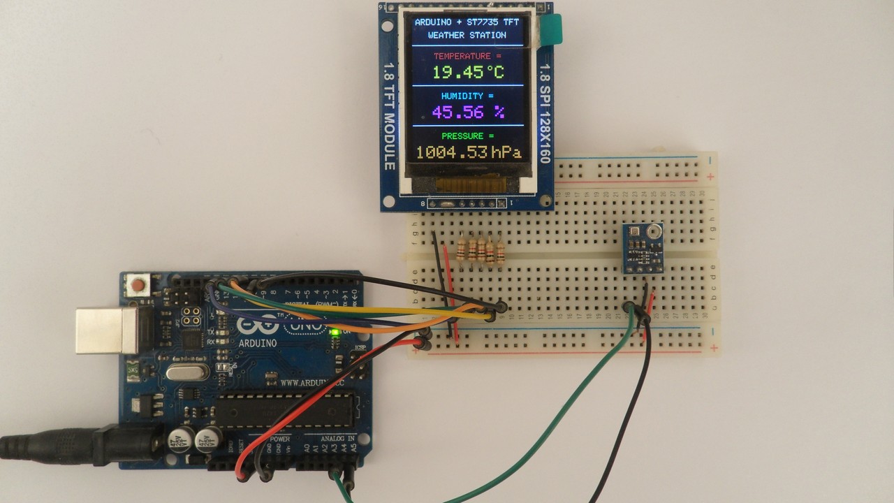
This post shows how to build weather station using Arduino UNO board and BME280 barometric pressure, temperature and humidity sensor.
The Arduino reads temperature & humidity & pressure values from the BME280 sensor and print them (respectively in °C & RH% & hPa) on ST7735 color TFT display.
The BME280 is a digital barometric pressure, temperature and relative humidity sensor from Bosch Sensortec. In this project the BME280 sensor is used in I2C mode.
The ST7735 TFT used in this project is a color display which has a resolution of 128×160 pixel and it communicates with the master device using SPI (Serial Peripheral Interface) protocol.
To see how to interface Arduino with ST7735 TFT display, visit the following post:
Arduino ST7735 1.8″ TFT display example
And to see how to interface Arduino with BME280 sensor for the first time, take a look at this post:
Arduino with BME280 pressure, temperature and humidity sensor
Hardware Required:
- Arduino uno board
- ST7735S (ST7735R) TFT display
- BME280 sensor module (with built-in 3.3V regulator and level shifter) —-> BME280 datasheet
- 5 x 1k ohm resistor
- Breadboard
- Jumper wires
Arduino weather station circuit:
The image below shows project circuit diagram.
Hint:
The BME280 chip works with maximum voltage of 3.6V (supply voltage range is from 1.71 to 3.6V) which means we’ve to use a 3V3 voltage regulator to supply it from a 5V source.
Also, if we’re working with a 5V system (development board, microcontroller …) like the Arduino UNO board (ATmega328P microcontroller), we’ve to use a voltage level shifter (level converter) which converts the 3.3V (comes from the BME280 chip) into 5V (goes to the ATmega328P) and vice versa. This level shifter is for the I2C bus lines (clock and data).
The BME280 module shown in project circuit diagram has a built-in 3.3V regulator and level shifter.
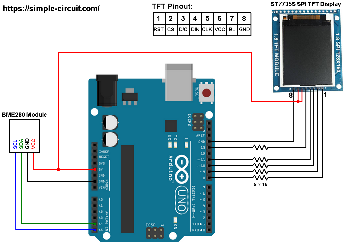
Generally, the BME280 module has at least 4 pins because it can work in SPI mode or I2C mode. For the I2C mode we need 4 pins: VCC, GND, SDA and SCL where:
GND (ground) is connected to Arduino GND pin,
VCC is the supply pin which is connected to Arduino 5V pin,
SDA is I2C bus serial data line, connected to Arduino analog pin 4 (A4),
SCL is I2C bus serial clock line, connected to Arduino analog pin 5 (A5).
The ST7735S shown in project circuit diagram has 8 pins: (from right to left): RST (reset), CE (chip enable), DC (or D/C: data/command), DIN (data in), CLK (clock), VCC (5V or 3.3V), BL (back light) and Gnd (ground).
Normally the ST7735 display works with 3.3V only, but many boards of this display have a built-in 3.3V regulator (AMS1117 3V3) like the one shown in the circuit diagram. This regulator supplies the display controller with 3.3V from 5V source.
All Arduino UNO board output pins are 5V, connecting a 5V pin directly to the ST7735 display board may damage its controller circuit. To avoid that, I connected each control line of the display to the Arduino board through 1k ohm resistor.
So, the ST7735 display is connected to the Arduino board as follows (each one through 1k resistor):
RST pin is connected to Arduino digital pin 8,
CS pin is connected to Arduino digital pin 9,
D/C pin is connected to Arduino digital pin 10,
DIN pin is connected to Arduino digital pin 11,
CLK pin is connected to Arduino digital pin 13.
Arduino weather station code:
The following Arduino code requires 3 libraries from Adafruit Industries:
The first library is a driver for the ST7735 TFT display, download link is below:
Adafruit ST7735 display library
The 2nd library is Adafruit graphics library which can be downloaded from the following link
Adafruit graphics library —-> direct link
The 3rd one is for the BME280 sensor:
Adafruit BME280 Library —-> direct link
You may need to install the Adafruit Unified Sensor library if it’s not already installed, download link is below:
Adafruit Unified Sensor library —-> direct link
After the download, go to Arduino IDE —> Sketch —> Include Library —> Add .ZIP Library … and browse for the .zip file (previously downloaded).
The same thing for the other library files.
The previous 3 libraries are included in the main code as follows:
1 2 3 | #include <Adafruit_GFX.h> // include Adafruit graphics library #include <Adafruit_ST7735.h> // include Adafruit ST7735 TFT library #include <Adafruit_BME280.h> // include Adafruit BME280 sensor library |
The ST7735 TFT display is connected to Arduino hardware SPI module pins (clock and data), the other pins which are: RST (reset), CS (chip select) and DC (data/command) are defined as shown below:
1 2 3 | #define TFT_RST 8 // TFT RST pin is connected to arduino pin 8 #define TFT_CS 9 // TFT CS pin is connected to arduino pin 9 #define TFT_DC 10 // TFT DC pin is connected to arduino pin 10 |
As any other I2C device, the BME280 sensor has an I2C slave address which may be 0x76 or 0x77. This address depends on the connection of the SDO pin (used for SPI mode as serial data out or MISO), if the SDO pin is connected (directly or through resistor) to VCC (3.3V) the address will be 0x77, and if it’s connected to GND the address will be 0x76.
The default I2C address of the BME280 library is defined as 0x77 and my device I2C address is 0x76.
In the code, the definition of BME280 sensor I2C slave address and the initialization of its library are as shown below:
1 2 3 4 | // define device I2C address: 0x76 or 0x77 (0x77 is library default address) #define BME280_I2C_ADDRESS 0x76 Adafruit_BME280 bme280; // initialize Adafruit BME280 library |
The initialization of the BME280 sensor is done using the function begin() which returns 1 if OK and 0 if error. In the code the initialization with the previously defined address is as shown below:
1 | bme280.begin(BME280_I2C_ADDRESS) |
Reading the values of temperature, humidity and pressure:
1 2 3 4 | // read temperature, humidity and pressure from the BME280 sensor float temp = bme280.readTemperature(); // get temperature in degree Celsius float humi = bme280.readHumidity(); // get humidity in rH% float pres = bme280.readPressure(); // get pressure in Pa |
Note that the BME280 sensor library returns the value of the pressure in Pa unit and to convert it to hPa we’ve to divide it by 100.
1 bar = 10000 Pa = 100 hPa. ( 1 hPa = 100 Pa = 1 millibar)
Pa: Pascal
hPa: hectoPascal
Temperature and pressure values are displayed on the ST7735 TFT display.
If there is a problem with the BME280 sensor (for example wrong device address) the screen will display Connection Error.
Full Arduino Code:
1 2 3 4 5 6 7 8 9 10 11 12 13 14 15 16 17 18 19 20 21 22 23 24 25 26 27 28 29 30 31 32 33 34 35 36 37 38 39 40 41 42 43 44 45 46 47 48 49 50 51 52 53 54 55 56 57 58 59 60 61 62 63 64 65 66 67 68 69 70 71 72 73 74 75 76 77 78 79 80 81 82 83 84 85 86 87 88 89 90 91 92 93 94 95 96 97 98 99 100 101 102 | /* * Arduino weather station with ST7735 color TFT display (128x160 pixel) and * BME280 barometric pressure, temperature & humidity sensor. * This is a free software with NO WARRANTY. * http://simple-circuit.com/ */ #include <Adafruit_GFX.h> // include Adafruit graphics library #include <Adafruit_ST7735.h> // include Adafruit ST7735 TFT library #include <Adafruit_BME280.h> // include Adafruit BME280 sensor library #define TFT_RST 8 // TFT RST pin is connected to arduino pin 8 #define TFT_CS 9 // TFT CS pin is connected to arduino pin 9 #define TFT_DC 10 // TFT DC pin is connected to arduino pin 10 // initialize ST7735 TFT library Adafruit_ST7735 tft = Adafruit_ST7735(TFT_CS, TFT_DC, TFT_RST); // define device I2C address: 0x76 or 0x77 (0x77 is library default address) #define BME280_I2C_ADDRESS 0x76 Adafruit_BME280 bme280; // initialize Adafruit BME280 library void setup(void) { tft.initR(INITR_BLACKTAB); // initialize a ST7735S chip, black tab tft.fillScreen(ST7735_BLACK); // fill screen with black color tft.drawFastHLine(0, 30, tft.width(), ST7735_WHITE); // draw horizontal white line at position (0, 30) tft.setTextColor(ST7735_WHITE, ST7735_BLACK); // set text color to white and black background tft.setTextSize(1); // text size = 1 tft.setCursor(4, 0); // move cursor to position (4, 0) pixel tft.print("ARDUINO + ST7735 TFT"); tft.setCursor(19, 15); // move cursor to position (19, 15) pixel tft.print("WEATHER STATION"); // initialize the BME280 sensor if( bme280.begin(BME280_I2C_ADDRESS) == 0 ) { // connection error or device address wrong! tft.setTextColor(ST7735_RED, ST7735_BLACK); // set text color to red and black background tft.setTextSize(2); // text size = 2 tft.setCursor(5, 76); // move cursor to position (5, 76) pixel tft.print("Connection"); tft.setCursor(35, 100); // move cursor to position (35, 100) pixel tft.print("Error"); while(1); // stay here } tft.drawFastHLine(0, 76, tft.width(), ST7735_WHITE); // draw horizontal white line at position (0, 76) tft.drawFastHLine(0, 122, tft.width(), ST7735_WHITE); // draw horizontal white line at position (0, 122) tft.setTextColor(ST7735_RED, ST7735_BLACK); // set text color to red and black background tft.setCursor(25, 39); // move cursor to position (25, 39) pixel tft.print("TEMPERATURE ="); tft.setTextColor(ST7735_CYAN, ST7735_BLACK); // set text color to cyan and black background tft.setCursor(34, 85); // move cursor to position (34, 85) pixel tft.print("HUMIDITY ="); tft.setTextColor(ST7735_GREEN, ST7735_BLACK); // set text color to green and black background tft.setCursor(34, 131); // move cursor to position (34, 131) pixel tft.print("PRESSURE ="); tft.setTextSize(2); // text size = 2 } // main loop void loop() { char _buffer[8]; // read temperature, humidity and pressure from the BME280 sensor float temp = bme280.readTemperature(); // get temperature in °C float humi = bme280.readHumidity(); // get humidity in rH% float pres = bme280.readPressure(); // get pressure in Pa // print temperature (in °C) if(temp < 0) // if temperature < 0 sprintf( _buffer, "-%02u.%02u", (int)abs(temp), (int)(abs(temp) * 100) % 100 ); else // temperature >= 0 sprintf( _buffer, " %02u.%02u", (int)temp, (int)(temp * 100) % 100 ); tft.setTextColor(ST7735_YELLOW, ST7735_BLACK); // set text color to yellow and black background tft.setCursor(11, 54); tft.print(_buffer); tft.drawCircle(89, 56, 2, ST7735_YELLOW); // print degree symbol ( ° ) tft.setCursor(95, 54); tft.print("C"); // 2: print humidity sprintf( _buffer, "%02u.%02u %%", (int)humi, (int)(humi * 100) % 100 ); tft.setTextColor(ST7735_MAGENTA, ST7735_BLACK); // set text color to magenta and black background tft.setCursor(23, 100); tft.print(_buffer); // 3: print pressure (in hPa) sprintf( _buffer, "%04u.%02u", (int)(pres/100), (int)((uint32_t)pres % 100) ); tft.setTextColor(0xFD00, ST7735_BLACK); // set text color to orange and black background tft.setCursor(3, 146); tft.print(_buffer); tft.setCursor(91, 146); tft.print("hPa"); delay(1000); // wait a second } // end of code. |
The following video shows a simple circuit of the project:


how to add a watch?
Do any of them(TFT_RST, TFT_CS, TFT_DC) relate to how text is displayed on the screen?
No, there’s no relation, if there’s a wrong connection the display may not work probably!
I built this project and got it up and running! My problem is that the on display text is backwards. The only change I made were to the pins CS, RST, and DC. If I didn’t I just get a white screen. Any ideas or suggestions? below is the code I used:
#define TFT_RST 9 // TFT RST pin is connected to arduino pin 8
#define TFT_CS 10 // TFT CS pin is connected to arduino pin 9
#define TFT_DC 8 // TFT DC pin is connected to arduino pin 10
The definition of TFT_RST, TFT_CS and TFT_DC pins depends on circuit connection.
Thank you verrrrry much for uploading video
Why dont you upload movie about circuit operation?
May be it will be later.
Thank you.