Drawing bitmap images (.BMP format) on ST7735 TFT display is quite easy because they are uncompressed images unlike JPEG images (.JPG format).
This post shows how to draw bitmap images on the ST7735 TFT using Arduino UNO board where the Arduino loads the BMP images from SD card and print them on the display.
The ST7735 TFT is a color display that uses SPI protocol, it has a resolution of 128×160 pixel. This display works with 3.3V only.
To see how to interface Arduino with ST7735 TFT display, visit the following post:
Arduino ST7735 1.8″ TFT display example
Hardware Required:
- Arduino UNO board
- ST7735S TFT display module
- microSD card with FAT16 or FAT32 file system
- microSD card module adapter
- Push button
- 5 x 1k ohm resistor
- Breadboard
- Jumper wires
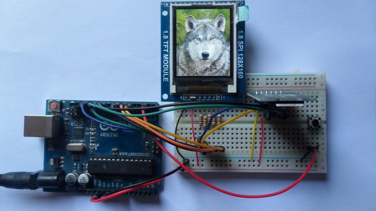
Arduino with ST7735 TFT and SD card circuit:
The following image shows project circuit diagram.
The ST7735S shown in project circuit diagram has 8 pins: (from right to left): RST (reset), CS (chip select), DC (or D/C: data/command), DIN (data in), CLK (clock), VCC, BL (back light) and Gnd (ground).
The ST7735S display module is supplied with 5V. GND pin is connected to Arduino GND pin, VCC and BL pins are connected to Arduino 5V pin.
In the display module there is AMS1117-3V3 voltage regulator which supplies the display controller with 3.3V (because it works with 3.3V only). The regulator steps down the 5V that comes from the Arduino board into 3.3V.

All Arduino UNO output pins are 5V, connecting a 5V pin directly to the ST7735 display board may damage its controller circuit. To avoid that, I connected each control line of the display to the Arduino board through 1k ohm resistor.
So, the ST7735TFT display is connected to the Arduino board as follows (each one through 1k ohm resistor):
RST pin is connected to Arduino digital pin 5,
CS pin is connected to Arduino digital pin 6,
DC pin is connected to Arduino digital pin 7,
DIN pin is connected to Arduino digital pin 11,
CLK pin is connected to Arduino digital pin 13.
In this project I used microSD card module, this module is supplied from circuit 5V source that comes from the Arduino UNO board. This module contains AMS1117-3V3 voltage regulator which is used to supply the micro SD card with 3.3V. Also this module contains an IC which is 74LVC125A and it’s used as level translator (from 5V to 3.3V).
The microSD card module is connected to the Arduino as follows (from left to right):
The first pin of the micro SD card module (GND) is connected to Arduino GND,
The second pin of the micro SD card module (VCC) is connected to Arduino 5V,
The third pin of the micro SD card module (MISO) is connected to Arduino digital pin 12,
The fourth pin of the micro SD card module (MOSI) is connected to Arduino digital pin 11,
The fifth pin of the micro SD card module (SCK) is connected to Arduino digital pin 13,
The last pin of the micro SD card module (CS) is connected to Arduino digital pin 10.
The digital pins 10, 11, 12 and 13 are hardware SPI module pins of ATmega328P microcontroller (Arduino UNO microcontroller). The SD card and the ST7735 TFT share the same SPI bus.
The button which is connected to Arduino digital pin 2 is used as ‘next image’, when pressed the display will show the next image.
Arduino with ST7735 TFT and SD card code:
As an addition to Arduino SPI library and SD library which are both built-in libraries (comes with Arduino IDE), the following code requires two libraries from Adafruit Industries:
The first library is a driver for the ST7735 TFT display which can be installed from Arduino IDE library manager (Sketch —> Include Library —> Manage Libraries …, in the search box write “st7735” and install the one from Adafruit).
The second library is Adafruit graphics library which can be installed also from Arduino IDE library manager.
Both libraries can be installed manually, first download them from the following 2 links:
Adafruit ST7735 TFT library —-> direct link
Adafruit graphics library —-> direct link
After the download, go to Arduino IDE —> Sketch —> Include Library —> Add .ZIP Library … and browse for the .zip file (previously downloaded).
The same thing for the other library file.
Hints:
There is no need to specify image names, the Arduino will search and draw all the BMP images located in the main root of the SD card.
The 4 libraries are included in the main code as shown below.
Including Arduino SPI library is optional!
1 2 3 4 | #include <Adafruit_GFX.h> // include Adafruit graphics library #include <Adafruit_ST7735.h> // include Adafruit ST7735 display library #include <SPI.h> // include Arduino SPI library #include <SD.h> // include Arduino SD library |
The ST7735 TFT module pins (RST, CS and DC) connections are defined as shown below:
1 2 3 4 | // define ST7735 TFT display connections #define TFT_RST 5 // reset line (optional, pass -1 if not used) #define TFT_CS 6 // chip select line #define TFT_DC 7 // data/command line |
The other display pins (DIN and CLK) are connected to Arduino hardware SPI pins (digital pin 11 and digital pin 13).
The Adafruit ST7735 library is initialized with this line:
1 2 | // initialize Adafruit ST7735 TFT library Adafruit_ST7735 tft = Adafruit_ST7735(TFT_CS, TFT_DC, TFT_RST); |
And the TFT display is initialized using the following command:
1 2 | // initialize ST7735S TFT display tft.initR(INITR_BLACKTAB); |
Rest of code is described through comments.
Full Arduino code:
1 2 3 4 5 6 7 8 9 10 11 12 13 14 15 16 17 18 19 20 21 22 23 24 25 26 27 28 29 30 31 32 33 34 35 36 37 38 39 40 41 42 43 44 45 46 47 48 49 50 51 52 53 54 55 56 57 58 59 60 61 62 63 64 65 66 67 68 69 70 71 72 73 74 75 76 77 78 79 80 81 82 83 84 85 86 87 88 89 90 91 92 93 94 95 96 97 98 99 100 101 102 103 104 105 106 107 108 109 110 111 112 113 114 115 116 117 118 119 120 121 122 123 124 125 126 127 128 129 130 131 132 133 134 135 136 137 138 139 140 141 142 143 144 145 146 147 148 149 150 151 152 153 154 155 156 157 158 159 160 161 162 163 164 165 166 167 168 169 170 171 172 173 174 175 176 177 178 179 180 181 182 183 184 185 186 187 188 189 190 191 192 193 194 195 196 197 198 199 200 201 202 203 204 205 206 207 208 209 210 211 212 213 214 215 216 217 218 219 220 221 222 223 224 225 226 227 228 229 230 231 232 233 234 235 236 237 238 239 240 241 242 243 244 245 | /* * Draw Bitmap images on ST7735 TFT display using Arduino. * The Arduino loads BMP format images from SD card and display * them on the ST7735 TFT. * Reference: Adafruit spitftbitmap.ino example. * This is a free software with NO WARRANTY. * http://simple-circuit.com/ */ #include <Adafruit_GFX.h> // include Adafruit graphics library #include <Adafruit_ST7735.h> // include Adafruit ST7735 display library #include <SPI.h> // include Arduino SPI library #include <SD.h> // include Arduino SD library // define ST7735 TFT display connections #define TFT_RST 5 // reset line (optional, pass -1 if not used) #define TFT_CS 6 // chip select line #define TFT_DC 7 // data/command line #define button 2 // button pin // initialize Adafruit ST7735 TFT library Adafruit_ST7735 tft = Adafruit_ST7735(TFT_CS, TFT_DC, TFT_RST); void setup(void) { Serial.begin(9600); pinMode(TFT_CS, OUTPUT); digitalWrite(TFT_CS, HIGH); pinMode(button, INPUT_PULLUP); // initialize ST7735S TFT display tft.initR(INITR_BLACKTAB); tft.fillScreen(ST77XX_BLUE); Serial.print("Initializing SD card..."); if (!SD.begin()) { Serial.println("failed!"); while(1); // stay here } Serial.println("OK!"); File root = SD.open("/"); // open SD card main root printDirectory(root, 0); // print all files names and sizes root.close(); // close the opened root } void loop() { File root = SD.open("/"); // open SD card main root while (true) { File entry = root.openNextFile(); // open file if (! entry) { // no more files root.close(); return; } uint8_t nameSize = String(entry.name()).length(); // get file name size String str1 = String(entry.name()).substring( nameSize - 4 ); // save the last 4 characters (file extension) if ( str1.equalsIgnoreCase(".bmp") ) // if the file has '.bmp' extension bmpDraw(entry.name(), 0, 0); // draw it entry.close(); // close the file delay(500); while( digitalRead(button) ) ; // wait for button press } } // This function opens a Windows Bitmap (BMP) file and // displays it at the given coordinates. It's sped up // by reading many pixels worth of data at a time // (rather than pixel by pixel). Increasing the buffer // size takes more of the Arduino's precious RAM but // makes loading a little faster. 20 pixels seems a // good balance. #define BUFFPIXEL 20 void bmpDraw(char *filename, uint8_t x, uint16_t y) { File bmpFile; int bmpWidth, bmpHeight; // W+H in pixels uint8_t bmpDepth; // Bit depth (currently must be 24) uint32_t bmpImageoffset; // Start of image data in file uint32_t rowSize; // Not always = bmpWidth; may have padding uint8_t sdbuffer[3*BUFFPIXEL]; // pixel buffer (R+G+B per pixel) uint8_t buffidx = sizeof(sdbuffer); // Current position in sdbuffer boolean goodBmp = false; // Set to true on valid header parse boolean flip = true; // BMP is stored bottom-to-top int w, h, row, col; uint8_t r, g, b; uint32_t pos = 0, startTime = millis(); if((x >= tft.width()) || (y >= tft.height())) return; Serial.println(); Serial.print(F("Loading image '")); Serial.print(filename); Serial.println('\''); // Open requested file on SD card if ((bmpFile = SD.open(filename)) == NULL) { Serial.print(F("File not found")); return; } // Parse BMP header if(read16(bmpFile) == 0x4D42) { // BMP signature Serial.print(F("File size: ")); Serial.println(read32(bmpFile)); (void)read32(bmpFile); // Read & ignore creator bytes bmpImageoffset = read32(bmpFile); // Start of image data Serial.print(F("Image Offset: ")); Serial.println(bmpImageoffset, DEC); // Read DIB header Serial.print(F("Header size: ")); Serial.println(read32(bmpFile)); bmpWidth = read32(bmpFile); bmpHeight = read32(bmpFile); if(read16(bmpFile) == 1) { // # planes -- must be '1' bmpDepth = read16(bmpFile); // bits per pixel Serial.print(F("Bit Depth: ")); Serial.println(bmpDepth); if((bmpDepth == 24) && (read32(bmpFile) == 0)) { // 0 = uncompressed goodBmp = true; // Supported BMP format -- proceed! Serial.print(F("Image size: ")); Serial.print(bmpWidth); Serial.print('x'); Serial.println(bmpHeight); // BMP rows are padded (if needed) to 4-byte boundary rowSize = (bmpWidth * 3 + 3) & ~3; // If bmpHeight is negative, image is in top-down order. // This is not canon but has been observed in the wild. if(bmpHeight < 0) { bmpHeight = -bmpHeight; flip = false; } // Crop area to be loaded w = bmpWidth; h = bmpHeight; if((x+w-1) >= tft.width()) w = tft.width() - x; if((y+h-1) >= tft.height()) h = tft.height() - y; // Set TFT address window to clipped image bounds tft.startWrite(); tft.setAddrWindow(x, y, w, h); for (row=0; row<h; row++) { // For each scanline... // Seek to start of scan line. It might seem labor- // intensive to be doing this on every line, but this // method covers a lot of gritty details like cropping // and scanline padding. Also, the seek only takes // place if the file position actually needs to change // (avoids a lot of cluster math in SD library). if(flip) // Bitmap is stored bottom-to-top order (normal BMP) pos = bmpImageoffset + (bmpHeight - 1 - row) * rowSize; else // Bitmap is stored top-to-bottom pos = bmpImageoffset + row * rowSize; if(bmpFile.position() != pos) { // Need seek? tft.endWrite(); bmpFile.seek(pos); buffidx = sizeof(sdbuffer); // Force buffer reload } for (col=0; col<w; col++) { // For each pixel... // Time to read more pixel data? if (buffidx >= sizeof(sdbuffer)) { // Indeed bmpFile.read(sdbuffer, sizeof(sdbuffer)); buffidx = 0; // Set index to beginning tft.startWrite(); } // Convert pixel from BMP to TFT format, push to display b = sdbuffer[buffidx++]; g = sdbuffer[buffidx++]; r = sdbuffer[buffidx++]; tft.pushColor(tft.color565(r,g,b)); } // end pixel } // end scanline tft.endWrite(); Serial.print(F("Loaded in ")); Serial.print(millis() - startTime); Serial.println(" ms"); } // end goodBmp } } bmpFile.close(); if(!goodBmp) Serial.println(F("BMP format not recognized.")); } // These read 16- and 32-bit types from the SD card file. // BMP data is stored little-endian, Arduino is little-endian too. // May need to reverse subscript order if porting elsewhere. uint16_t read16(File f) { uint16_t result; ((uint8_t *)&result)[0] = f.read(); // LSB ((uint8_t *)&result)[1] = f.read(); // MSB return result; } uint32_t read32(File f) { uint32_t result; ((uint8_t *)&result)[0] = f.read(); // LSB ((uint8_t *)&result)[1] = f.read(); ((uint8_t *)&result)[2] = f.read(); ((uint8_t *)&result)[3] = f.read(); // MSB return result; } void printDirectory(File dir, int numTabs) { while (true) { File entry = dir.openNextFile(); if (! entry) { // no more files break; } for (uint8_t i = 0; i < numTabs; i++) { Serial.print('\t'); } Serial.print(entry.name()); if (entry.isDirectory()) { Serial.println("/"); printDirectory(entry, numTabs + 1); } else { // files have sizes, directories do not Serial.print("\t\t"); Serial.println(entry.size(), DEC); } entry.close(); } } // end of code. |
This project was tested with original Samsung 32GB and 4GB micro SD cards.
The following video shows my breadboard test circuit:
And this one shows project Proteus simulation:
Note that Proteus simulation circuit is not the same as real hardware circuit, project hardware circuit diagram is shown above.
Proteus simulation file download link is below, use version 8.6 or higher to open it:
download
SD Card image file download (images are included):
download
Bitmap images download link:
download
Images are downloaded from https://wallpaper.mob.org/


Thanks for posting this! Lifesaver! I used an st7789 and it worked just fine, just set the initializer to st7789 and also include the adafruit st7789.h. My colors did come out inverted so I had to also add a tft.invert(0) command. Thanks again!
Hello,
is it possible to play the images in the other direction. horizontally instead of vertical..
Hello, Thank you for your information. I have problem. I used winimage program but i have error. SD card failed. I dont know it. Do u have any idea?
Everything works very well. But I would also like to display a graphic and simple text. If I first display the generated txt and graphically and then the images (.bmp) everything is still ok. But when I switch back to the graphic, it is displayed very pale and fuzzy. Only after a restart I can see the text and graphics again rich in contrast.
How would you go about making this automated (with a delay) instead of using a button to rotate the images?
Good day.
Everything works, thanks!
Have display 128×128, in the settings have taken INITR_144GREENTAB.
hey this Code is work for Eink Display ?
i would love to know that too!
Hello, How to load custom image on sd card? can anyone did it
I bought a little SD card reader for my laptop. This allowed me to upload the images to it.
Hello the code has an error? It says ‘no matching function for call to ‘SDClass::begin()’
Try another library from ST7735, or replace begin () with init ()
Sorry, other library from SD.h
What library do you use?
Hello,
I’m trying to do your project with an Arduino UNO, the same SD module but with a 0.96 “7-pin screen and I can’t get it to work.
Any advice?? For example, how do I have to put the pins on the screen?
Thank you
Hola,
Estoy tratando de hacer su proyecto con un Arduino UNO, el mismo módulo SD pero con una pantalla de 0.96” de 7 pines y no consigo que funcione.
Algún consejo?? por ejemplo, cómo tengo que poner los pines de la pantalla?
Gracias